Eclipse 8/ 16/ 32 Series - Engineer Programming Manual
76
To select all areas press button “0” – the button alternatively switches over all enabled / all disabled
state.
Keyboards and modules: If all areas for a device are disabled the device becomes inactive,
irrespective there are any options programmed for it. If the device is a keyboard then it can perform
only engineer and maintenance programming, and the manager and user programming are disabled
as and the arming and disarming operations with it.
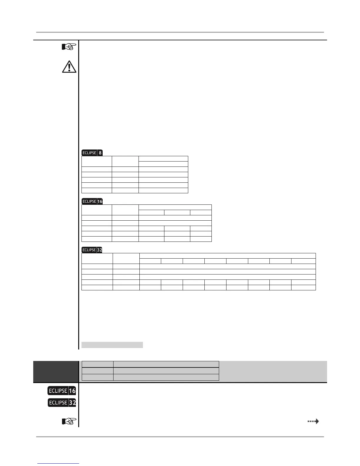
LED 8: The keyboard supports operation with one area only. If more than one area are set at this
address for LED8 keyboard, then only the area with the smallest number will be active.
LED 16A: The keyboard supports operation with three areas named А, В and С. If more than three
areas are set at this address for LED 16A keyboard, then only the three areas with the smallest
numbers will be active.
Proximity card readers: If all areas for the reader are disabled at this address, then the device will
operate only in MODE A and MODE B set at addresses 8xx7 and 8xx8.
You must consider the following important notes for Eclipse Series Keyboards, when design and organize the
security system including ECLIPSE panels!
One Area: No specific indication
Two Areas: A and B indication
One Area: No specific indication
Two Areas: A and B indication
Three Areas: A, B and C indication
* Note: The area number is set at address 8xx3, where “xx” is the keyboard number in the system.
** Note: The area numbers are set at address 8xx3, where “xx” is the keyboard number in the system. The areas are
displayed as A and B, where A is the area with the smaller number, and B - the area with higher one. Note that there may not
be direct correspondence between the area number and the keyboard indication letter.
*** Note: LED 16 A keyboard supports operation with three independent areas in the system. The area numbers are set at
address 8xx3, where “xx” is the keyboard number in the system. The areas are displayed as A, B and C where A is the area
with the smaller number, and C - the area with higher one. Note that there may not be direct correspondence between the
area number and the keyboard indication letter.
Default setting: AREA 1
9. DEVICES – 02. DEVICE [Name] – 3. OPTIONS
Setting of options for Device 02
A set of options are programmed at the address for Device 02. The options are selected with
pressing the respective digit button. The next pressing the same button deselects the option. More
than one option can be programmed. The final choice is confirmed with ENTER.
The options from 1 to 4 can be programmed only for the connected to the system bus