Eclipse 8/16/32/99 Series - Installation Manual
11
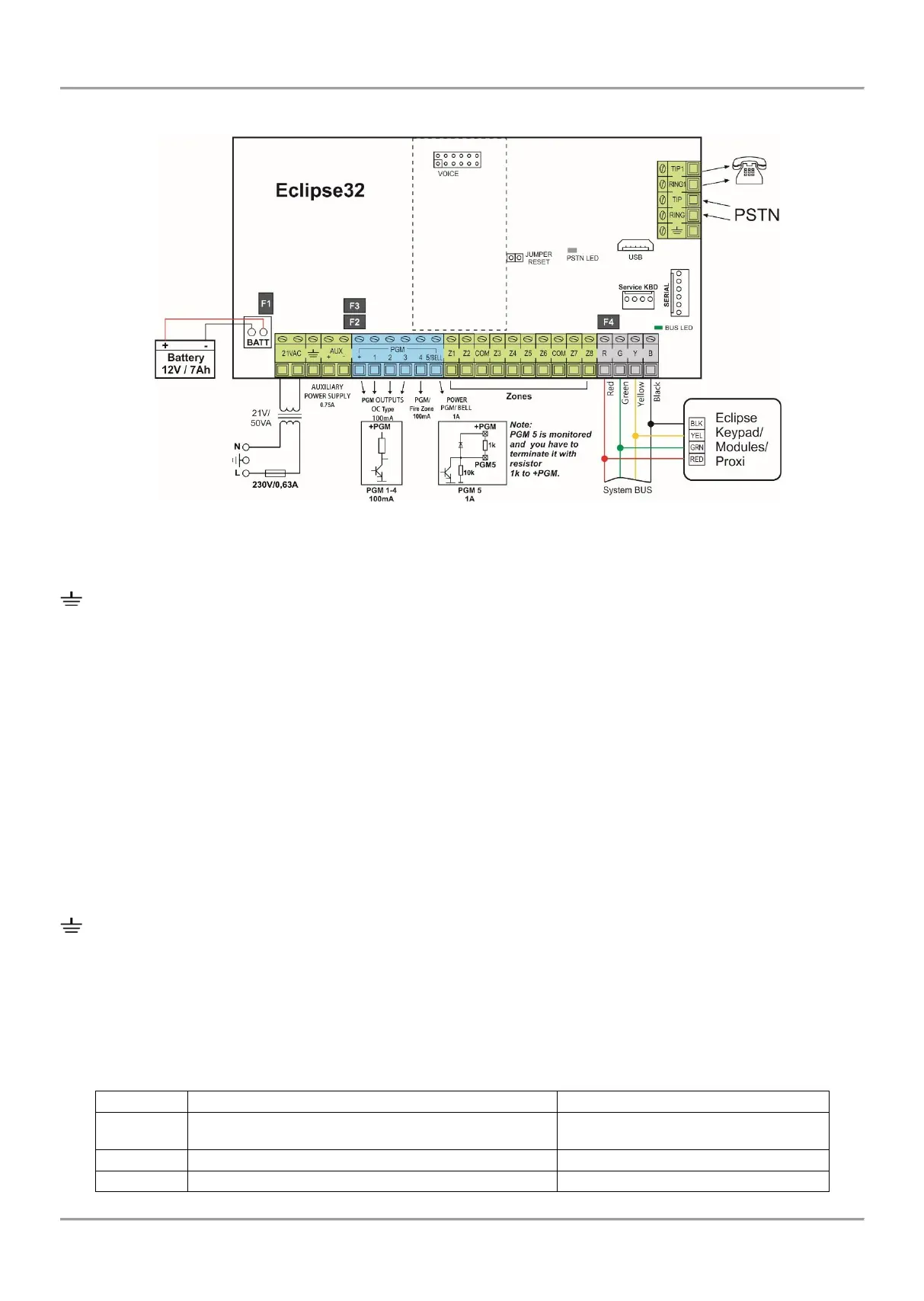
2.2.3 ECLIPSE 32
Figure 7. ECLIPSE 32 control panel
ECLIPSE 32 - Terminals and components:
21VAC – Power supply from a mains transformer 21V/50VA, fuse 0.63А
– Grounding
+/- AUX – Power supply for detectors with consumption up to 0.75А
+PGM – Power supply of auxiliary devices with consumption up to 0.75А
PGM 1-3 – Programmable outputs, 100mA, ОС type (open collector)
PGM 4 – Programmable output/Fire zone (programmed at Menu 3. Programmable outputs), 100mA, ОС type (open collector)
PGM 5/BELL – Monitored programmable output, high power up to 1А, ОС type (open collector), for connecting siren
Z1-Z8 – Zone inputs
COM – Common ground for the zones
R(red), G(green), Y(yellow), B(black) - System bus interface for connection of keyboards, proximity card readers, expanders,
etc.
Jumper RESET – Jumper for total hardware reset of the control panel
Serial – Interface for PC connection
Service KBD – Connecting a service keyboard – see also item 6 (available for HW 1.8 and higher)
VOICE - Interface connector for mounting of Voice module ECLIPSE VD
BATT – Terminals for connecting the back-up battery
USB – Micro USB port for programming with ProsTE software (available for HW 2.3 and higher)
PSTN terminals:
TIP1, RING1 – Connect the telephone device
TIP, RING – Connect the PSTN line
– Grounding
Fuses, PTC type:
F1 – Fuse for the back-up battery: 2.5A
F2 – Fuse for PGM outputs: 0.75A
F3 – Fuse for AUX outputs: 0.75A
F4 – Fuse for the system bus: 0.5А
LED indication:
• PSTN LED – LED for the status of the built-in digital communicator.
• BUS LED – LED for the status of the system bus: