The ECLIPSE Series expander modules are connected to the system bus. Every module is available in two variants:
a) PCB with power supply from the control panel (ZONE 8 and PGM 8);
b) PCB with own power supply (ZONE 8 PS and PGM 8 PS)
The Eclipse modules ZONE 8 and PGM 8 can be situated in the panel’s box – see Figures 1 and 3 - or into a separate
small plastic box SB-U (sold separately).
ATTENTION: It is possible to mount the ZONE 8 and PGM 8 modules under the main PCB of ECLIPSE 32 only!
The Eclipse modules ZONE 8 PS and PGM 8 PS are designed for mounting in big box with transformer unit and 230V
terminal.
• Installation in the box of ECLIPSE 32 control panel
ATTENTION: The full configuration of 32 zones in ECLIPSE 32 can be realized with doubling zone connection (16 logical zones on the control PCB)
and 1 Zone expander for 8 zones (16 logical zones) or without zone doubling with connection of 3 zone expanders to the panel.
Remove the PCB of the ECLIPSE 32 control panel – the PCB is secured with two clips from both sides.
Mount the expander module PCB to the bottom of the box:
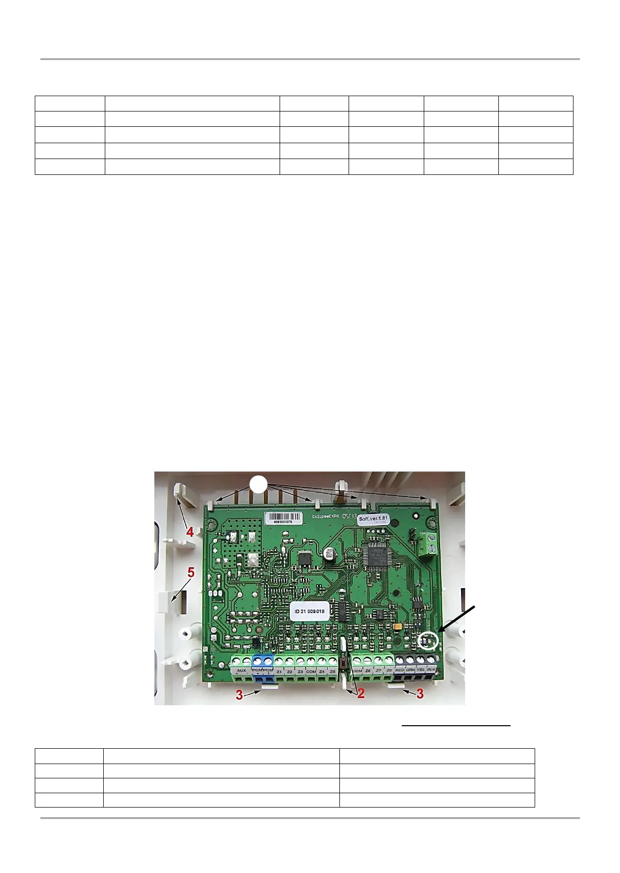
1. Fix the upper side of the PCB into the holders as shown on the Figure 17.
2. The pins of the bottom must fit in the PCB openings.
3. Press the PCB of the expander downwards to secure with the clips.
4. Mount back the PCB of the ECLIPSE 32 control panel above the expander – fix it into the upper holders (4)
and press down to secure in the side clips (5).
5. Connect the 8-Zone Expander to the ECLIPSE 32 serial system bus as observe the polarity – see Figures
13 and 14.
Figure 17. Example for mounting of expander module in the ECLIPSE 32 panel box
• LED indication of expander modules ZONE 8, PGM 8, ZONE 8 PS and PGM 8 PS