Eclipse 8/16/32/99 Series - Installation Manual
18
2.4.2 Supported Keyboards
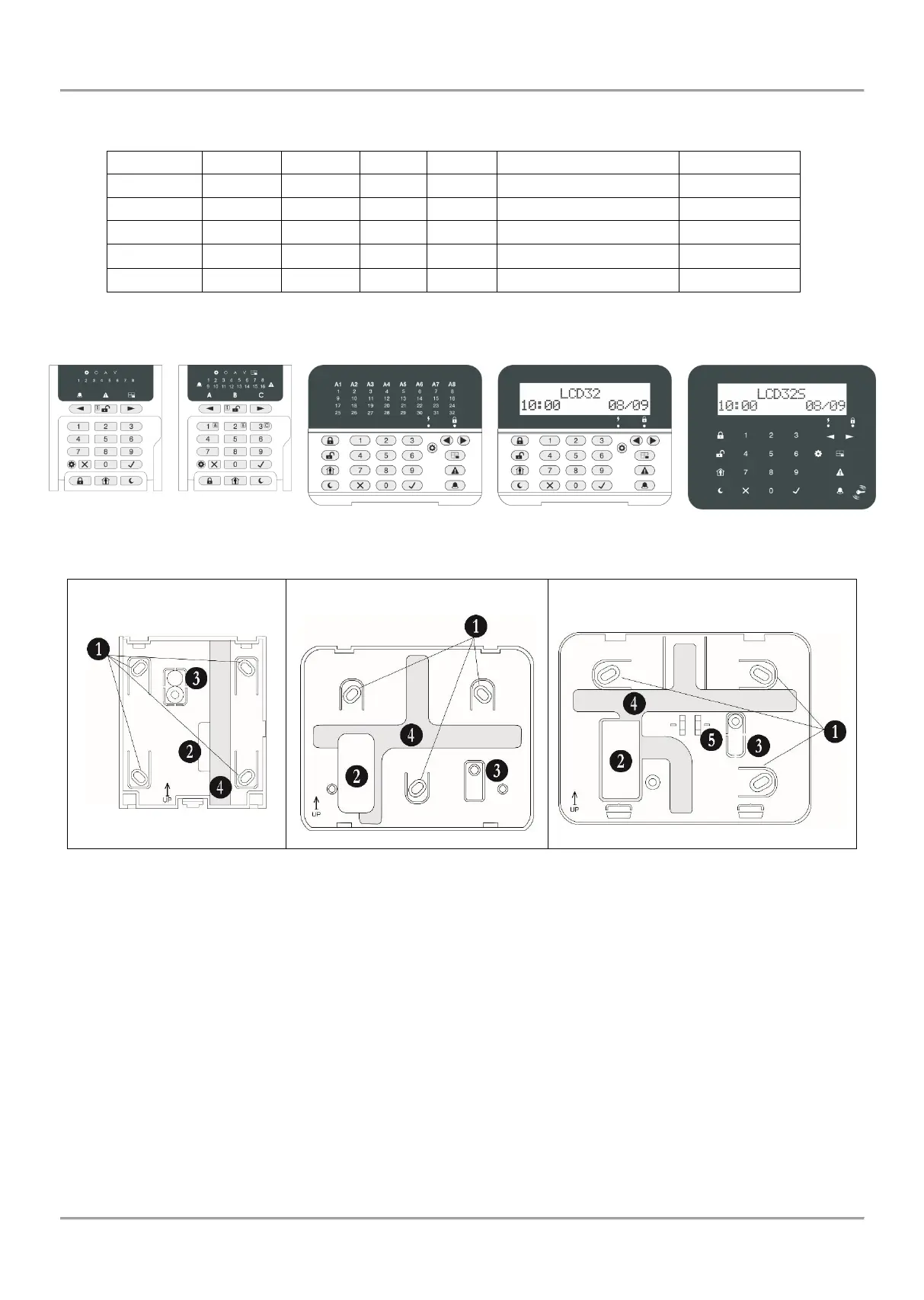
Summary for ECLIPSE Series Keyboards:
Figure 16. Rear panels of ECLIPSE Series Keyboards
• Description of the keyboard rear panel elements:
1. Mounting holes
2. Main opening for cable running
3. Tamper plate. Fix the plate with a screw to the mounting surface. In case of unauthorized attempt for
demounting the keyboard, the tamper plate will break out and release the tamper-switch on the keyboard’s PCB.
4. Special cable channels on the back side of the rear panel.
5. Lever holder.
• Keyboard terminals:
RED, GREEN, YELLOW, BLACK - System bus interface for connection to control panel
Zone – Independent full functional keyboard zone with freely programmable parameters. It can be used as additional
zone to control panel and must be attached to a zone number at address 2xx0 (xx is the zone number) with the
respective number of the device.
GND – Common ground
PGM (LCD 32 and LCD 32 Sensitive) – Programmable output, 100mA, OC type