EasyManua.ls Logo

Teletek electronics ECLIPSE 8 - User and Area Management

Teletek electronics ECLIPSE 8
40 pages
Print Icon
To Next Page IconTo Next Page
To Previous Page IconTo Previous Page
Loading...
Eclipse 8/16/32/99 Series - Installation Manual
27
2.5. Connection of PGM Outputs
ECLIPSE Control Panels Series PGM capability:
Control panel
Max. PGM outputs
Power output, up to 1A
PGM Additional Functionality
ECLIPSE 8
5
1 (PGM 5), non-monitored
PGM 4 - Serial link to TP2000 transmitter
ECLIPSE 16
8
1 (PGM 5), non-monitored
N.A.
ECLIPSE 32
32
1 (PGM 5), monitored
PGM 4 - Fire zone for 24V standard fire base
ECLIPSE 99
99
1 (PGM 5), monitored
PGM 4 - Fire zone for 24V standard fire base
In the ECLIPSE series alarm panels PGM1, PGM2, PGM3 and PGM4 outputs have a programmable active level. This
allows them to be used to transmit control signals towards external devices (e.g. a block siren input) or to directly
control low-powered external devices (e.g. relays, LED, etc.).
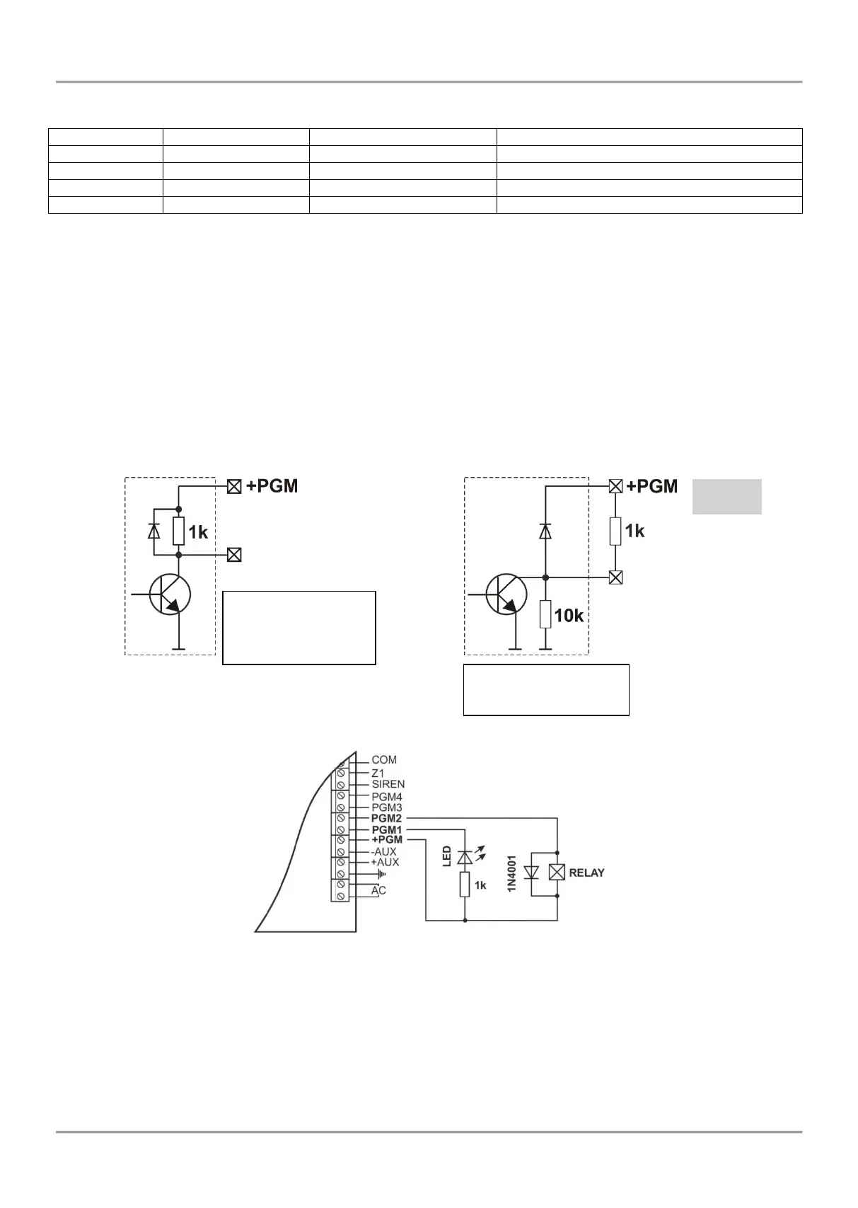
The internal structure of all PGMs (excepting PGM5 in ECLIPSE 32 and ECLIPSE 99) is the same and is shown on
Figure 20 a).
The internal structure of PGM5 in ECLIPSE 32 and ECLIPSE 99, is shown on Figure 20 b).
Important: PGM5 output in ECLIPSE 32 and ECLIPSE 99 control panels are monitored and when are used it is
obligatory to be terminated with 1k resistor to +PGM terminal.
Figure 20 c) shows the connection of the relay and a light-emitting diode to the PGM. The active level of this
connection is low.
Figure 20. Internal structure of PGM output and example for connection of LED
c)
PGMx Terminal
Permissible current:
- from +12V - to 10mA
- from GND - to 100 mA
- PGM5 (ECLIPSE 32/99) -
up to 1A
For output PGM 5/Bell the
permissible current to GND
is up to 1 A.
a)
b)
PGM5/Bell
ECLIPSE 32
ECLIPSE 99

Other manuals for Teletek electronics ECLIPSE 8

Related product manuals