Eclipse 8/16/32/99 Series - Installation Manual
17
2.4. Connection of Peripheral Devices
2.4.1 Connection to the System Bus
ECLIPSE Control Panels Series – DEVICE capability:
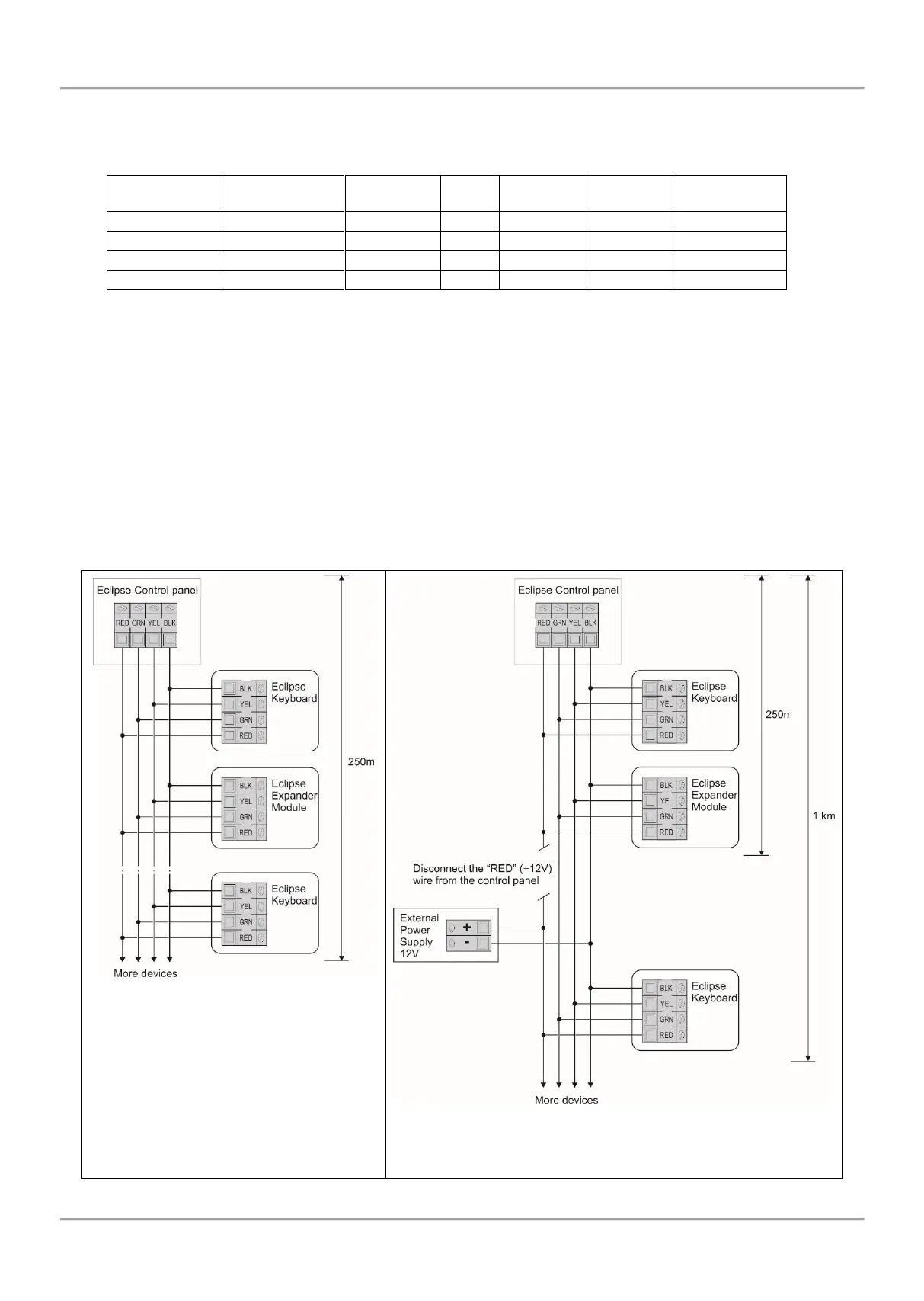
All ECLIPSE Series peripheral devices are connected to the system bus – power and data terminals, located at the
right bottom corner and labeled as: B - Black (0V), R - Red (+12V), Y - Yellow and G - Green (both for data transfer).
When connecting devices to the system bus, assure first to turn off the main and the backup power supply of the
control panel and strictly observe the polarity of wires as shown on Figure 13.
The maximal distance between the control panel and the last device on the system bus is 250m without using external
power supply. Keep in mind that this distance might be shorter and depends on the number of peripheral devices
connected to the bus. The great number of devices will cause voltage drop in the cable. Refer to the technical
specification tables for used keyboards and expander modules to calculate the possible consumption of your system
and the expected voltage drops.
For cable distances exceeding 250m (up to 1km) you need an external 12V power supply source connected to the
system bus – B (black) (0V) and R (red) (+12V) terminals. Refer also to the connection diagram on Figure 14.
Figure 13. Connecting of peripheral
devices (up to 250 meters cable length,
no external power supply needed)
Figure 14. Connecting of peripheral devices (up to 1 km
cable length, with external power supply)