Eclipse 8/16/32/99 Series - Installation Manual
20
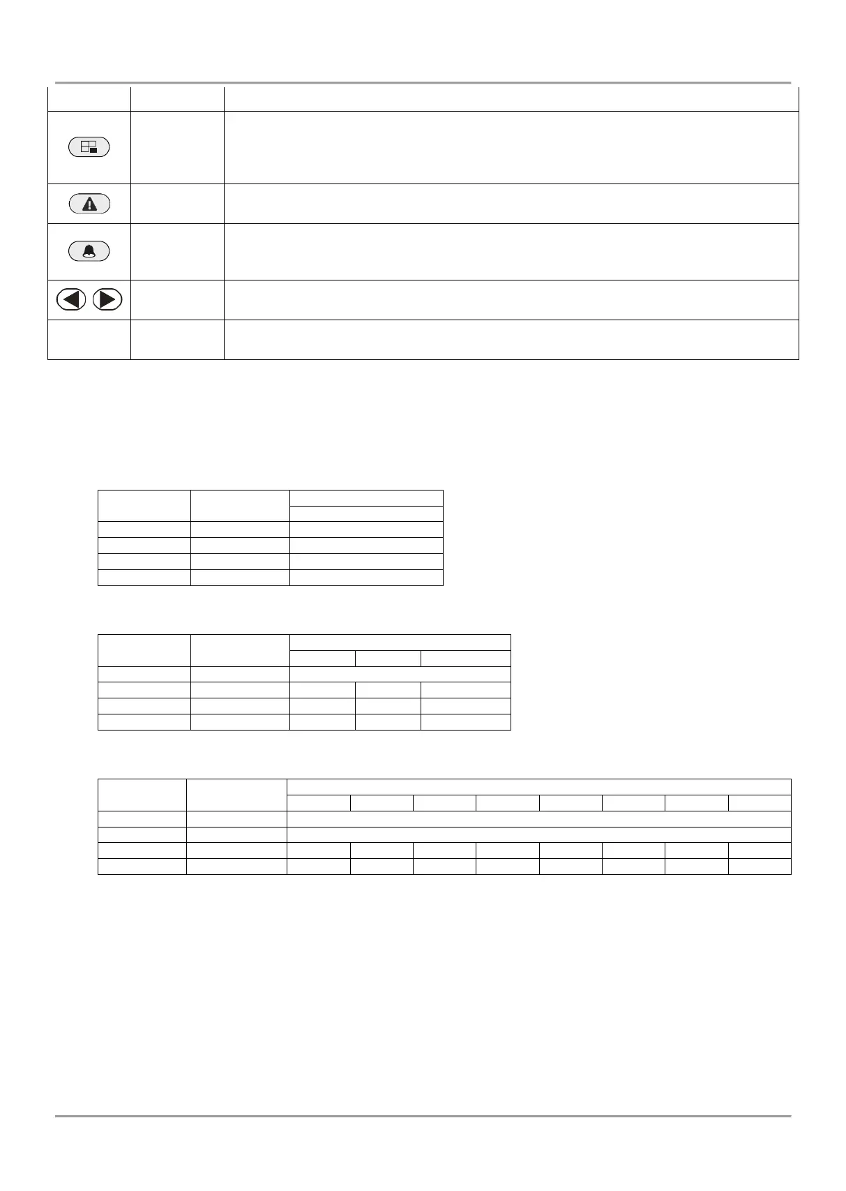
settings and moves forward as the current index number is increased with +1.
Bypassing zones. The button lights on permanently if there are bypassed zones in the
system. The button is blinking during the bypassed zones review.
The button has a special function in engineer programming – canceling the entered
settings and moves forward as the current index number is increased with +1, option 0.
Reviewing the system troubles. The button lights on permanently if there are system
problems. The button is blinking during the system troubles review.
Reviewing the memory events log file. The button lights on permanently if there are
memory events. The button is blinking during the memory events review. The button has a
special function in text entering mode – entering of special symbols.
Arrows for moving the cursor on the left and on the right in programming mode.
Digital buttons for entering parameters, codes, etc.
• Correspondence between the ECLIPSE panels and the supported areas from keyboards
You must consider the following important notes for Eclipse Series Keyboards, when design and organize the security
system including ECLIPSE panels!
ECLIPSE 8:
One Area: No specific indication
One Area: No specific indication
Three Areas: A, B and C indication
* Note: LED 8 keyboard supports operation with only one area in the system. The area number is set at address 8xx1, where “xx” is
the keyboard number in the system.
** Note: LED 16A keyboard supports operation with three independent areas in the system. The area numbers are set in menu
9.DEVICES-XX.Device-2.AREA (address 8xx1), where “xx” is the keyboard number in the system. The areas are displayed as A, B
and C, where A is the area with the smaller number, and C - the area with higher one. Note that there may not be direct
correspondence between the area number and the keyboard indication letter.
*** Note: When connected to Eclipse 99 the installer can associate up to 8 areas to one LED32 keyboard. The area numbers are set
in menu 9.DEVICES-XX.Device-2.AREA (address 8xx1), where “xx” is the keyboard number in the system. The areas are displayed
as A1-A8, where A1 is the area with the smaller number, and A8 - the area with higher one. Note that there may not be direct
correspondence between the area number and the keyboard indication letter.