INSTRUMENT MANUAL
VACUUM GAUGE MODEL MM200
160Phone:(215) 947-2500 fax:(215) 947-7464 e-mail:sales@televac.com web site:www.televac.com
MM-200_im REV M
Page 140 of 160
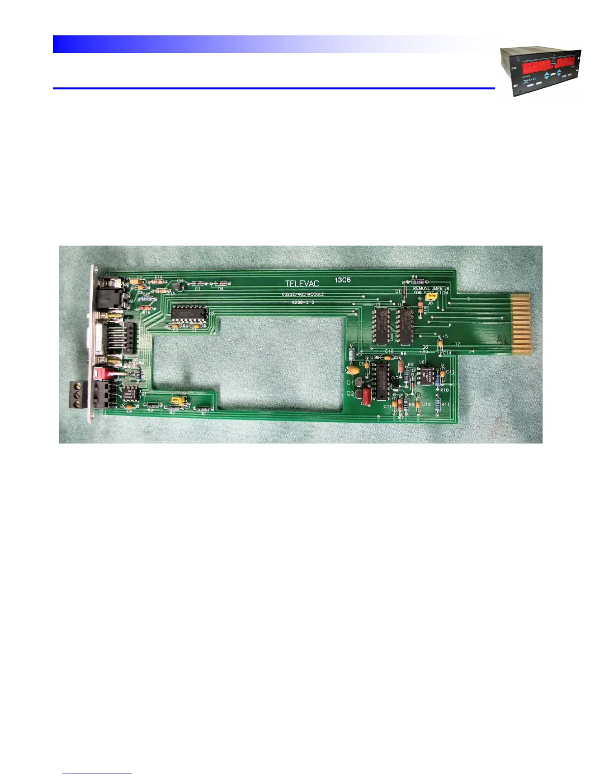
DIGITAL INTERFACE MODULE - A digital interface module is shown in Fig. 9.2. When a cold cathode module is
installed in expansion slot #6, it must be removed before the digital interface module can be installed. Note that
there is a cutout in the digital interface module to clear the transformer of the cold cathode module. These two
modules must be installed at the same time.
RSS485 allows a string of MM200s to be linked. It is important to terminate the last unit on the string. This is done
by placing a jumper across J6 (TERM) in the lower left hand side of the board. This termination is designed for 120
± ohm twisted pair cable. If another value (such as 220 ohm) cable is used, change the value of R2 from 121 ohms
to the appropriate value.
Fig. 9.2 – Digital Interface Module