INSTRUMENT MANUAL
VACUUM GAUGE MODEL MM200
160Phone:(215) 947-2500 fax:(215) 947-7464 e-mail:sales@televac.com web site:www.televac.com
MM-200_im REV M
Page 141 of 160
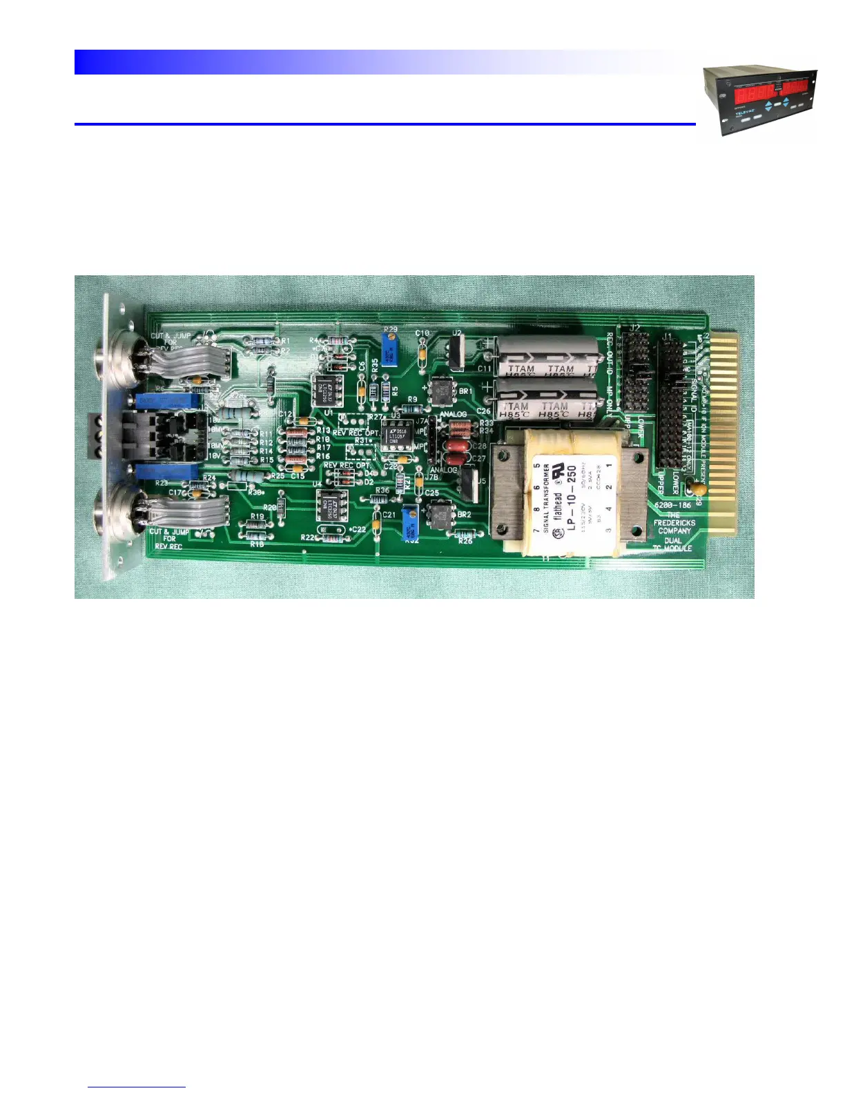
THERMOCOUPLE MODULE - A thermocouple module is shown in Fig. 9.3a and 9.3b. This module is typical of all
modules. The assignment of station identification numbers on a thermocouple module is accomplished by placing
jumpers across the appropriate pins in the SIGNAL ID and the REC OUT ID sections. The upper thermocouple
station has been named station #3 and the lower thermocouple station has been named station #4. Also two (2)
jumpers are placed in the "MP" positions of the ANALOG/MP section of the board.
Fig. 9.3a - Thermocouple Module