Telewave, Inc.
Model 44A/AP
Page 7
4 FUNCTIONAL DESCRIPTION
4.01 The Model 44A/AP Wattmeter is made up of two major sections.
Refer to the schematic diagram in Figure 3-1 for this description.
(a) A Dual RF Directional Coupler with directivity of greater than
25 dB.
(b) A voltmeter circuit. Five ranges are provided.
4.02 The 50 ohm Dual Directional Coupler A1 samples a small amount
of the incident or forward RF power delivered to the load. The cou-
pler incorporates two RF detectors which produce a DC voltage
proportional to the sampled RF power. A small amount of power
refl ected from the load is also sampled.
4.03 Mode Switch S1 determines which of these voltages is displayed on
the meter, M1. The RF Power Range Switch S2, selects the appro-
priate range and calibration resistors for the power to be measured.
Each range is provided with an adjustable internal potentiometer for
range calibration.
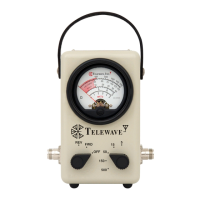
4.04 Meter M1 displays fi ve scales which correspond to the RF Power
Range Switch positions. The lower third of the meter scale is shaded
red, alerting the user to switch to a lower power range for full instru-
ment accuracy. An OFF position is provided on Mode Switch S1,
which shunts out the meter movement. This provides protection for
the sensitive meter when the instrument is being transported.
4.05 Model 44AP provides an RF sampling port with an output of -40 dB
(+/- 2 dB) below the transitional line level to use for measurement
of frequency, spectrum analysis, to inject a signal for measurement
of receiver sensitivity, or other applications. The port coupling is
not directional; in a high VSWR system, the sampling port output
will be -40 dB below the total power passing through the instru-
ment.