Telewave, Inc.
Model 44A/AP
Page 10
Step Procedure
2 Set the RF Range Switch to the 500 Watt position.
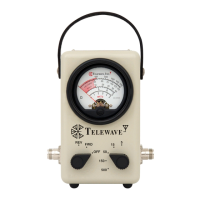
3 Connect the RF Source to the Model 44A/AP FWD input
connector, located on the left side of the instrument nearest the
mode switch.
4 Connect the RF Load to the Model 44A/AP FWD output
connector, located on the right side of the instrument nearest the
range switch.
Forward Power Measurement
5.03 The following procedure will assist the user in making an incident
or forward power measurement. Refer to Figure 2-1.
Step Procedure
1 Set the Mode Switch to the FWD position.
2 Apply RF power to the transmission line.
3 Move the RF Range Switch to a lower range if necessary to
obtain a reading in the upper two-thirds of the scale.
4 Note the meter reading. Apply appropriate correction factor
if the frequency is between 20-150 MHz. Refer to Figure 7-2.
Refl ected Power Measurement
5.04 The following procedure will assist the user in making a refl ected
or reverse power measurement.
Step Procedure
1 Set the Mode Switch to the REV position.
2 Repeat Step 2 of 5.03.
3 Repeat Step 3 of 5.03.
4 Repeat Step 4 of 5.03.