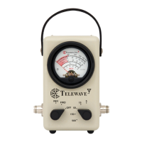
Telewave, Inc.
Model 44A/AP
Page 2
1 SPECIFICATIONS
1.01 Table 1-1 lists specifi cations for the Telewave Model 44A/AP
Broadband RF Wattmeter. These are provided to assist the user in
formulating acceptance criteria, determining applications, and for
periodic recalibration of the instrument. Minor deviations from
these specifi cations which do not affect performance of the Model
44A/AP Wattmeter should not be considered a warranty issue.
Table 1-1: Model 44A/AP RF Wattmeter Specifi cations
Parameter Characteristics
Frequency Range
Accuracy
20 to 150 MHz
150 to 1000 MHz
20 to 1000 MHz
(Specifi ed with N connectors only)
± 6 percent with Figure 7-2 curve.
± 6 percent
(Accuracy specifi ed at 80% of full scale
after application of correction factor if any)
Power Ranges 5, 15, 50, 150 and 500 Watts
Primary Line Impedance
VSWR
Insertion Loss
50 Ohms nominal
1.1 maximum
0.1 dB maximum
RF Sample Port (44AP) -40 dB +/- 2 dB
RF Connectors
Standard
Optional
QC - “Quick-Change” type
N-Female
UHF, BNC, TNC, 7-16 DIN M/F
Note: UHF connectors reduce measurement
accuracy in the 400 to 1000 MHz range.
Dimensions
Height
Width
Depth
Weight
6.625 in. (16.83 cm)
4 in. (10.16 cm)
3.25 in. (8.26 cm)
3 lbs. (1.36 kg)