Do you have a question about the TELEWAVE 44A and is the answer not in the manual?
Details electrical and physical characteristics, including frequency range, accuracy, and power ranges.
Outlines the wattmeter's primary features, operating principles, and overall design.
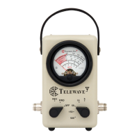
Details the function of each numbered control and indicator on the device, referencing Figure 2-1.
Provides the RF wattmeter's schematic diagram and a comprehensive list of its components.
Explains the operation of the directional coupler, meter, switches, and RF sampling port.
Lists common accessories available for the Model 44A/AP Wattmeter, such as carry cases and RF loads.
Procedures for inspecting the wattmeter and making proper RF connections for measurements.
Step-by-step guide for performing incident, forward, and reflected power measurements.
Method for determining Voltage Standing Wave Ratio using a chart or formula.
Method for calculating actual power delivered to the load by subtracting reflected power.
Discussion of potential measurement errors due to coupler directivity and jumper cable impedance.
Details the one-year warranty, return procedures, and contact information for repairs.
Identifies the location of adjustment potentiometers and components within the wattmeter for calibration.
Outlines the equipment setup, requirements, and steps for calibrating the wattmeter.
Nomograph for estimating VSWR from incident and reflected power readings.
Chart providing correction factors for power measurements at frequencies below 150 MHz.
Chart of RG-213 jumper cable lengths for specific frequencies to minimize VSWR errors.
The Telewave Model 44A/AP is a Broadband RF Wattmeter designed for measuring incident and reflected radio frequency (RF) power across a wide frequency range. This instrument is a robust, lightweight, and portable device, suitable for field use, including mobile, marine, aircraft applications, and base stations. It operates without the need for AC power or batteries, as its measurement circuits are driven directly by the current developed in its internal couplers.
The Model 44A/AP Wattmeter integrates two broadband directional couplers for measuring incident and reflected power, ranging, calibration, and display. It features a 20 µA taut band meter movement for displaying measured power, ensuring accuracy for tuning low-power portable transmitters. The instrument eliminates the need for inserts or band switching, offering wide coverage and dynamic range.
The device's core components include a Dual RF Directional Coupler with a directivity greater than 25 dB and a voltmeter circuit with five selectable ranges. The 50-ohm Dual Directional Coupler samples a small amount of the incident (forward) RF power delivered to the load and also samples power reflected from the load. Two RF detectors within the coupler produce a DC voltage proportional to the sampled RF power.
A Mode Switch (S1) determines whether the meter (M1) displays forward or reflected power. An RF Power Range Switch (S2) selects the appropriate power range and calibration resistors. Each power range has an adjustable internal potentiometer for calibration. The meter M1 displays five scales corresponding to the RF Power Range Switch positions. The lower third of the meter scale is shaded red, indicating that the user should switch to a lower power range for optimal accuracy. An "OFF" position on the Mode Switch S1 shunts out the meter movement, protecting the sensitive meter during transport.
The Model 44AP variant includes an RF sampling port with an output of -40 dB (+/- 2 dB) below the transitional line level. This port can be used for external measurements such as frequency analysis, spectrum analysis, or injecting a signal for receiver sensitivity measurements. It's important to note that the sampling port coupling is not directional; in high VSWR systems, its output will be -40 dB below the total power passing through the instrument.
The Model 44A/AP is designed for ease of use. To perform an RF power measurement:
For forward power measurement:
For reflected power measurement, the process is similar, but the Mode Switch is set to REV.
The instrument includes a VSWR Chart on its rear for quick estimation of Voltage Standing Wave Ratio from measured forward and reflected power. For higher accuracy, a formula is provided. True power at the load can be calculated by subtracting reflected power from incident power.
The device is fully operable in freezing conditions, making it suitable for diverse environments. It features interchangeable "Quick-Change" (QC) connectors for versatility. A leather carrying strap is integrated for portability, and an optional carrying case (Model TC44) is available.
The Model 44A/AP Wattmeter is built with high-reliability components and operates at low DC power levels, ensuring long intervals of peak performance. Periodic calibration by Telewave or an RF standard laboratory is recommended to maintain optimal instrument performance.
The instrument is covered by Telewave's standard 1-year warranty. For warranty service, faulty units should be returned to Telewave, Inc. A Return Material Authorization (RMA) is required for all returns, which necessitates providing the serial number, date of purchase, a brief problem statement, and contact/shipping information.
Adjustments to the instrument should be performed by Telewave or another qualified RF calibration laboratory. Calibration is ideally performed at 467 MHz. If calibration is necessary below 150 MHz, a correction factor (Figure 7-1) must be applied. Adjustment potentiometers for each power range (R1, R2, R3, R6, R7, R10, R11, R14, R15, R18) are located on the main PC board inside the instrument.
Calibration requires specific equipment and conditions:
A correction factor is required for measurements below 150 MHz, as detailed in the manual's frequency chart. Users are cautioned not to drive the meter beyond full scale or apply more than 500 watts input power at any time.
To access the adjustment potentiometers, the four bumper screws and the rear panel must be removed. The manual provides detailed steps for both Forward and Reverse Mode Adjustments across all power ranges, using specific RF source outputs and adjusting corresponding potentiometers.
To minimize insertion error in high VSWR systems, especially when using a jumper cable, the manual provides a chart (Figure 7-3) for determining the required length of RG-213/U cable (including N connectors) to act as a 1/2 wave line section at frequencies from 25-500 MHz. This ensures the jumper cable and wattmeter together approximate a 1/2 wavelength equivalent at the test frequency.
| Brand | TELEWAVE |
|---|---|
| Model | 44A |
| Category | Measuring Instruments |
| Language | English |