Telewave, Inc.
Model 44A/AP
Page 15
6.05 Calibration / Adjustment Requirements and Equipment
a) The ambient temperature during calibration must be 72.4
degrees.
b) The Telewave meter must be calibrated in the intended operating
position, either vertical or horizontal. Meters are calibrated by
Telewave in the vertical position
.
c) The Telewave wattmeter and any interconnections must use only
Type N connectors.
d) An RF power source capable of producing at least 325 watts
continuous power at 467 Mhz.
e) A low pass fi lter capable of handling at least the maximum
continuous power used during calibration must be installed
between the RF source and the Telewave meter.
f) A calibrated digital power meter and remote sensor, with
accuracy of +/- 0.5% or better, traceable to NIST. Insertion loss
of all test equipment must be characterized.
g) A 50 ohm inline attenuator capable of handling the maximum
continuous power that will be used during calibration.
Note: A correction factor is required for measurements at frequencies
below 150 MHz. The specifi ed power level is fed to the Telewave watt-
meter, and the correct percentage factor from the frequency chart on Page
19 in the manual is added to the displayed power measurement.
Measurement tolerance: +/- 6% of measured reading at 80% of full scale
after application of correction factor (if any).
Caution: Do not drive the meter beyond full scale, and do not apply
more than 500 watts input power at any time.
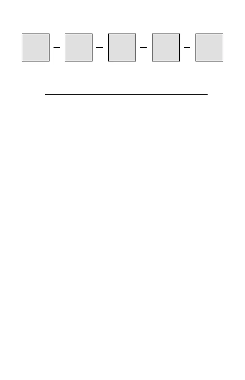
Figure 6-2: Calibration / Adjustment Equipment Setup
Variable
RF Power
Source
Low
Pass
Filter
Model 44A
Under
Calibration
In-Line
Calibrated
Attenuator
Power
Sensor
► ► ►►