Telewave, Inc.
Model 44A/AP
Page 11
VSWR Calculation
5.05 The following procedure will assist the user in determining the
Voltage Standing Wave Ratio.
Step Procedure
1 Perform the procedures outlined in 5.03 and 5.04. Record the
true incident and refl ected power.
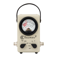
2. Refer to the VSWR Chart on the rear of the instrument or Figure
7-1. Apply the readings from Step 1 to the chart.
3. The VSWR is read from the nearest sloping line. For higher
accuracy, calculate the VSWR by the formula:
True Power at Load Calculations
5.06 The following procedure will assist the user in determining the
actual power delivered to the load.
Step Procedure
1 Perform the procedures outlined in 5.03 and 5.04. Record the
true incident and refl ected power.
2 Subtract the refl ected power from the incident power.
This difference is the true power at the load.
VSWR =
1 +
P
REV
(Watts)
P
FWD
(Watts)
1 -
P
REV
(Watts)
P
FWD
(Watts)