Telewave, Inc.
Model 44A/AP
Page 5
3 PHYSICAL DESCRIPTION
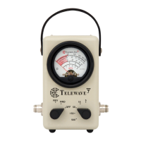
3.01 The controls and indicators of the Model 44A/AP Broadband RF
Wattmeter are illustrated in Figure 2-1, and the functions of these
elements are described in Table 3-1.
Key Item Description
1 Carry Strap For carrying or hanging the instrument.
2 Identifi cation Label
Contains model and serial number of the
instrument.
3 Meter Displays measured power.
4 Sample Port
Connection point for external measure-
ment or signal injection (Model 44AP).
5 Input Connector
Connection point for the RF source, such
as an RF power amplifi er or transmitter.
Mates with Type N or UHF connector
(typical).
6 Output Connector
Connection for the RF load, such as an an-
tenna or dummy load. Mates with Type N
or UHF connector (typ.)
7 Mode Switch
(1) OFF – Transit. Provides protection
for meter during instrument
movement.
(2) FWD – Displays forward or incident
power.
(3) REV – Displays the refl ected power.
8 Power Range Switch Selects one of 5 full scale power ranges.
9 VSWR Chart
Provides a method to calculate VSWR
from the measured forward and refl ected
power.
10 Correction Factor
Provides a method to determine the scale
correction for measurements below 150
MHz.
Table 3-1 : Model 44A/AP Description