56033504 © 2007 Telular Corporation
11
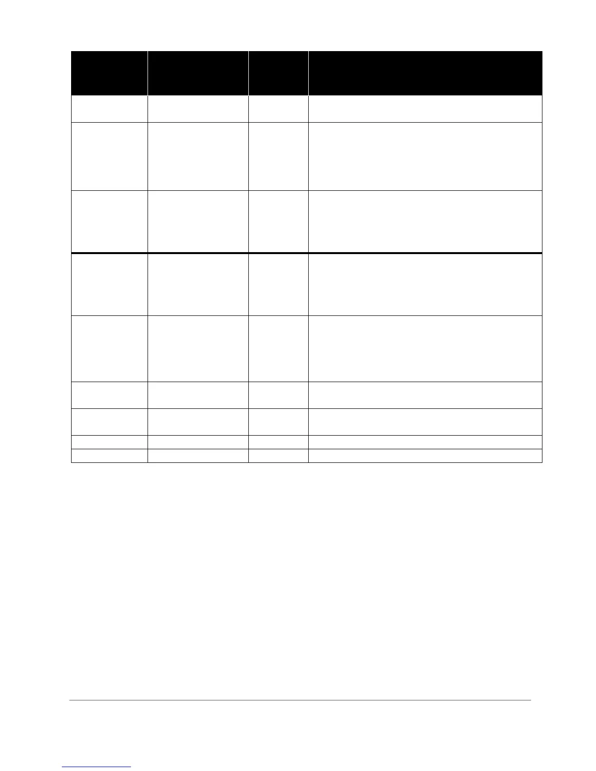
MEMORY
LOCATION
FIELD DEFAULT
VALUE
SETTING
831
Mode of operation
1 1 = Telco Primary/Cellular Backup
2 = Cellular Primary/Telco Backup
833
C/C Reporting Format
09
01= 4x2 pulse, 40pps 2300 hz 02= 4x2 pulse, 20pps 2300 hz
03= 4x2 pulse, 20pps 1400 hz 04= 3x1 pulse, 40pps, 2300 hz
05= 3x1 pulse, 20pps, 2300 hz 06= 3x1 pulse, 10pps, 1400 hz
07= Radionics IIe or IIIa
2
08 = Contact ID
09 = Auto Format Detect
11 = SIA2 (300 Baud) 12 = DMP
850
STC 1 Trip Output
Reporting
Normally
Open
04
Enter the SUM TOTAL of the events that you wish to trip the
STC relay by ADDING the corresponding values:
00 = STC Trip Input Not Used
01 = AC Failure 04 = LFC 16 = RFC
02 = Low Battery 08 = NSC 31 = All
851
STC 2 Trip Output
Reporting
Normally
Closed
27
Enter the SUM TOTAL of the events that you wish to trip the
STC relay by ADDING the corresponding values:
00 = STC Trip Input Not Used
01 = AC Failure 04 = LFC 16 = RFC
02 = Low Battery 08 = NSC 31 = All
852
STC Trip Delay for LFC
and NSC
2
1=30 seconds 6=30 minutes
2=60 seconds 7=45 minutes
3=3 minutes 8=60 minutes
4=10 minutes 9=24 hours
5=20 mintues
861
CFC Number of Events
0
0 = disabled 2 = 4 attempts
1 = 2 attempts 3 = 8 attempts
862
CFC between Events
1
1 = 30 seconds 3 = 70 seconds 5 = 90 seconds
2 = 60 seconds 4 = 80 seconds 6 = 99 seconds
872
AC Failure Delay
02
0-24 hours, default = 2 hours
899
Factory Default Unit
5.4.2 Disconnect telco line (RJ-31x
Jack) from Telguard Jack J6 (GRAY Connector)
Disconnect the plug from J6 (gray) of the Telguard that goes to the RJ-31x Jack at the premise.
5.4.3 Verify Alarm Signal Transmissions over Cellular
Trip several alarms on the C/C and verify that the central station received them by calling the central station
operator. Use a lineman's buttset in MONITOR MODE and connected to Telguard's "T" and "R" test pins to
"listen" to communications between the C/C and Telguard. The ACK LED #4 will come on solid while waiting
for an acknowledgement.
If you are having problems getting reliable alarm signal transmissions, additional adjustments may be
necessary.
♦ Recheck signal strength. You need RSSI = 2½ (TWO LEDS ON SOLID AND THE THIRD LED
FLASHING) for adequate signal strength. Also, check antenna connector and make sure it is seated
correctly.
♦ Call Telular Technical Service, 1-800-229-2326 extension 9, and request the Telular Communication
Center operator to check the Telguard programming configuration for proper operation and proper
communications format.