56033504 © 2007 Telular Corporation
16
A1.4 LED MODES AND FUNCTIONS
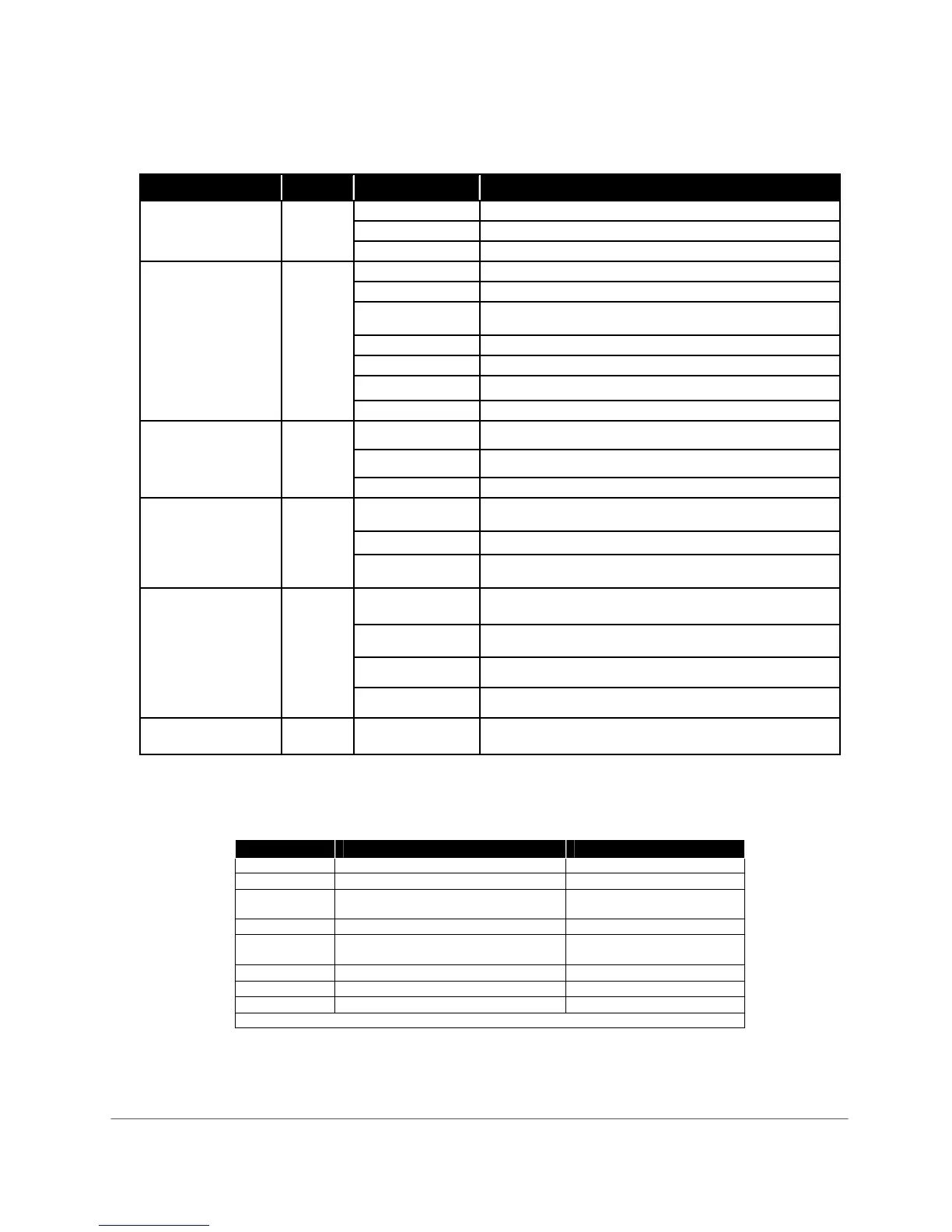
LED Function Table – Normal Operating Mode (J10 = OPEN)
LED Symbol Color Duty Cycle Indication
LED #1 Solid On Unit is registered with the message center and enabled
Registration Off Unit not registered with message center (and disabled)
Green
Flashing Unit is registered but disabled
LED #2 OFF ALL OK
STC 1 Flash* System Trouble Condition – Low/Missing AC Power
2 Flashes* System Trouble Condition – Low/Missing Battery Condition
AND/OR Battery Charger Failure
3 Flashes* System Trouble Condition – LFC
4 Flashes* System Trouble Condition – NSC
5 Flashes* System Trouble Condition – RFC
(System Trouble
Condition)
Red
6 Flashes* System Trouble Condition – DTF
Off Mode 2, Cell Priority
On Mode 1, Telco Priority
LED #3
MODE
Yellow
Fast Flash C/C off-hook to transmit signals over cellular.
LED #4
Acknowledgement
Solid On Telguard waiting for acknowledgement from Communication
Center
Off Idle state
Red
Flashing When flashing with LED #1 unit has failed registration due to
the programming of the panel, CALL TECH SUPPORT
LED #5
Radio
Off TG-4 initialized
On TG-4 initializing & registering with cellular network or
Transmitting Alarm Data
Short Flash (1 sec) Radio receiving message
Green
Long Flash (2 sec) Radio sending message
LED #6
AC Power
Red Solid On AC power connected to unit
LED Function Table – View RSSI Mode (J10 = SHORTED)
RSSI Value LED’s Lighted RF dBm
NO SVC LED 5 = slow flash, LED 4-2 = off n/a
1 LED 5 = on, LED 4-2 = off
≤ -111 dBm
1½ LED 5 = on, LED 4 = slow flash
LED 3-2 = off
≥ -110 dBm
2 LED 5-4 = on, LED 3-2 = off
≥ -100 dBm
2½ LED 5-4 = on, LED 3 = slow flash
LED 2 = off
≥ -90 dBm (Minimum signal
strength required)
3 LED 5-3 = on, LED 2 = off
≥ -80 dBm
3½ LED 5-3 = on, LED 2 = slow flash
≥ -70 dBm
4 LED 5-2 = on
≥ -60 dBm
Note: LED #1 = on indicates more than one cellular tower.