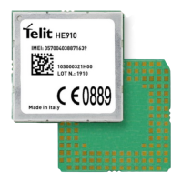
HE910 Hardware User Guide
1VV0300925 Rev. 32 Page 6 of 111 2019-11-25
5.3.2. Thermal Design Guidelines ......................................................... 47
5.3.3. Power Supply PCB layout Guidelines ......................................... 48
6. GSM/WCDMA RADIO SECTION ............................................... 50
HE910 Product Variants ............................................................. 50
TX Output Power ........................................................................ 51
Sensitivity ................................................................................... 51
GSM/WCDMA Antenna Requirements ....................................... 52
GSM/WCDMA - PCB line Guidelines .......................................... 53
PCB Guidelines in case of FCC certification ............................... 55
6.6.1. Transmission line design ............................................................ 55
6.6.2. Transmission line measurements ............................................... 56
GSM/WCDMA Antenna - Installation Guidelines ......................... 58
Antenna Diversity Requirements ................................................. 58
7. GPS RECEIVER ......................................................................... 60
GPS Performances ..................................................................... 60
GPS Signals Pinout .................................................................... 61
RF Front End Design .................................................................. 62
7.3.1. RF Signal Requirements ............................................................. 62
7.3.2. GPS Antenna Polarization .......................................................... 63
7.3.3. GPS Antenna Gain ..................................................................... 64
7.3.4. Active versus Passive Antenna ................................................... 64
7.3.5. GPS Antenna - PCB Line Guidelines .......................................... 65
7.3.6. RF Trace Losses ........................................................................ 65
7.3.7. Implications of the Pre-select SAW Filter .................................... 65
7.3.8. External LNA Gain and Noise Figure .......................................... 66
7.3.9. Powering the External LNA (active antenna) ............................... 66
7.3.10. External LNA Enable .................................................................. 66
7.3.11. Shielding ..................................................................................... 67
7.3.12. GPS Antenna – Installation ......................................................... 67
8. LOGIC LEVEL SPECIFICATIONS ............................................. 68
Unconditional Shutdown ............................................................. 70
9. USB PORT ................................................................................. 72
USB 2.0 HS Description .............................................................. 72
10. SPI PORT ................................................................................... 73
SPI Connections ......................................................................... 73

 Loading...