www.temcoline.com
DIGITAL PID CONTROLLER
7. Check Points before Using
1) Default values at the point of manufacture
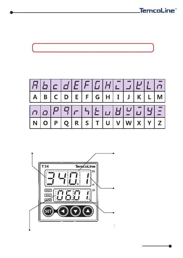
2) 7 Segment display indications
3) Initial display on power supply (T34 SERIES basis)
Model Name
Firmware version display
Option indication
Output type indication
Input type indication
0 : Basic type (No option)
1 :
RET, ALARM1, 2
3 : DI(SV1, 2), ALARM1, 2
01 : K-Type (-200~1370 ℃)
02 :
K-type (-199.9~999.9 ℃)
33 : mV DC (0~100 mV)
16
The default input and output values of the product at the point of
manufacture are as follows.
Input : K-Type (Code No. 1) Output : SSR (Code No. 1)
※ In the case of the basic model of T34-S00 only, when SSR(1) or
SCR(2) is chosen as the output mode, Alarm 1 output will be in main
relay. (Refer to page 8 for details.)
0 : RELAY ON/OFF control
1 :
SSR (
VOLT-PULSE) PID control
2 : SCR (4~20mA) PID control
3 : RELAY PID control

 Loading...