- 5 -
7.3 Control via Modbus RTU communications
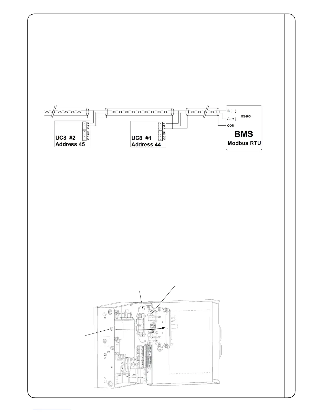
Single or multiple HWP units can be fully monitored and controlled via Modbus RTU serial communications. The
following is typical for most installations:
• Set DIP switches 11 and 12 OFF on the UC8 controller.
• Connect BMS terminal A / TX+ to terminal A1 on the UC8 controller.
• Connect BMS terminal B / TX- to terminal B1 on the UC8 controller.
It is recommended to ‘daisy-chain’ the A&B connections using shielded twisted pair type cable, suitable for RS485
communications. Signals A and B should form one twisted pair. The cable shield should connect to terminal ‘0V’ on the
UC8 controller.
• To avoid collisions of messages on the RS485 serial communications cable it is necessary to ensure each connected
UC8 controller has a unique Modbus device address. Refer to section 7.4 for the procedure.
Example:
For detailed information about monitoring and control via Modbus RTU refer to document “UC8 Modbus
communications” available at www.temperzone.biz; model search 'UC8'.
7.4 Setting the UC8 Modbus device address
To view or change the Modbus device address of a UC8 follow these steps:
• Power up the unit but leave the compressor off.
• Hold down the pushbutton on the UC8, release the button as soon as the display shows the letter ‘A’.
• The display will show the current Modbus device address. The factory default address is 44. Press the button to select
higher numbers, for example press once to change the address to 45, press twice for address 46 and so forth. After
address 99 the number returns back to 1.
• When the desired address is selected wait for 30 seconds. The controller will save the selected address in memory.
7.5 Run Status / Fault monitoring
UC8 includes a Run Status monitoring output signal. The output is active when one of the following conditions apply:
• the compressor is on
• the indoor fan is on
• the compressor and indoor fan are currently off but the thermostat is on, ie the unit is in deadband, or the compressor
may be held off by an internal safety timer or by a protection function.
A non-specic Fault monitoring output signal is also available. Refer Troubleshooting (9.7) regarding fault codes.
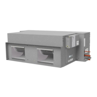
CONTROLS
Run (SRB) and Fault (FRB) relays for client connection are
located here on the back side of the UC8 mounting plate
UC8 mounting plate
shown swivelled for access
Release screw – for
UC8 mounting plate
Typical Electrical Box