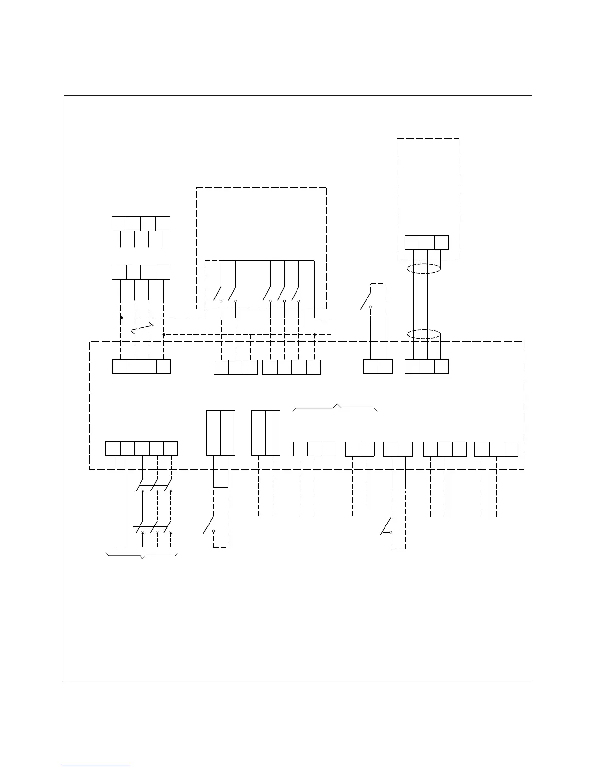
Wiring Schematic
MARKETING SERVICES 29.6.17 Revision F
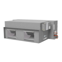
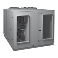
HWP Unit
12
B
A
0V
12V
B
A
GND
SAT-3
UC8
UC8
UC8
UC8
24
B
A
24C
TZT-100*
Room T/stat Options
24V AC
option*
Alternative
compatible
3 speed
thermostat
or
BMS
(independently
powered)
Hi
Me
Lo
C1
E
N
L1
L2
L3
Power Supply
1Ø (2 core+E)
or
3Ø (4 core+E)
depending on unit
External
Protection
Isolator
HIGH
MED
LOW
COMP
HEAT
On
0V
Optional
Remote On/Off
(remove link if used)
CP
HT
C2
Optional
Water Flow Verfication
switch (normally open)
(remove link if used)
WATER FLOW1
WATER FLOW2
link
WATER PUMP1
WATER PUMP2
Optional
Circulating Pump Control output
AC only, max. 0.25A RMS
(voltage free solid state relay
contacts)
N/O
C
N/C
Relay 1
Optional
Open/Close Flow Valve output
(voltage free dry relay contacts)
Optional
Condensate Lift-Pump output
(voltage free dry relay contacts)
N/O
C
Relay 2
D1
SC
UC8
Optional
Condensate Drain Tray
float switch (normally closed)
(remove link if used)
Optional
Communicating
BMS Controller
Modbus RTU
12V DC
option*
B1
A1
0V
B
A
REF
Control
- shielded
twisted pair
2 core + screen
link
Control
- shielded
twin twisted pair
4 core
*Use either option; NOT both.
* For all HWP models set TZT-100
DIP switches 2 & 4 to ON,
DIP3 to OFF.
UC8
(AUX/SRB)
Optional
Run Status
UC8
(FLT/FRB)
Optional
External Fault Alarm
N/O
C
N/C
N/O
C
N/C