Page 11 of 24
Heat Pump Water Heaters
MWP Series
Piping
The MWP Heat Pump should be located at close proximity to
the pool, pump and lter as practicably possible. Keep pipe
length as short as possible with as few bends and restrictions
as possible. Restricted ow may result in high pressure faults
occurring. Connecting pipework may be insulated to minimize
heat losses and prevent freezing in sub-zero ambient. The Heat
Pump must be installed after the water lter and before the
chlorinator.
The titanium thermoshell heat exchanger has a very low water
pressure drop in operation so a secondary boost water pump
should not be required for most residential applications but may
be required for commercial applications. The pool pump should
be sized to provide sufcient ow for the operation of the heat
pump. If the pump ow is excessive for the heat pump
operation, then that excess ow may be bypassed around the
heat pump via a balancing valve per the included schematic.
Model Water IN & OUT Connections Nominal water ow rate
MWP 230 1
1
/
2
” (38mm) PVC union 125 l/min. (2.08 l/s)
MWP 250 1
1
/
2
” (38mm) PVC union 130 l/min. (2.16 l/s)
MWP 400 2” (50mm) PVC union 200 l/min. (3.33 l/s)
MWP 800 2” (50mm) PVC union (2 pair) 400 l/min. (6.66 l/s)
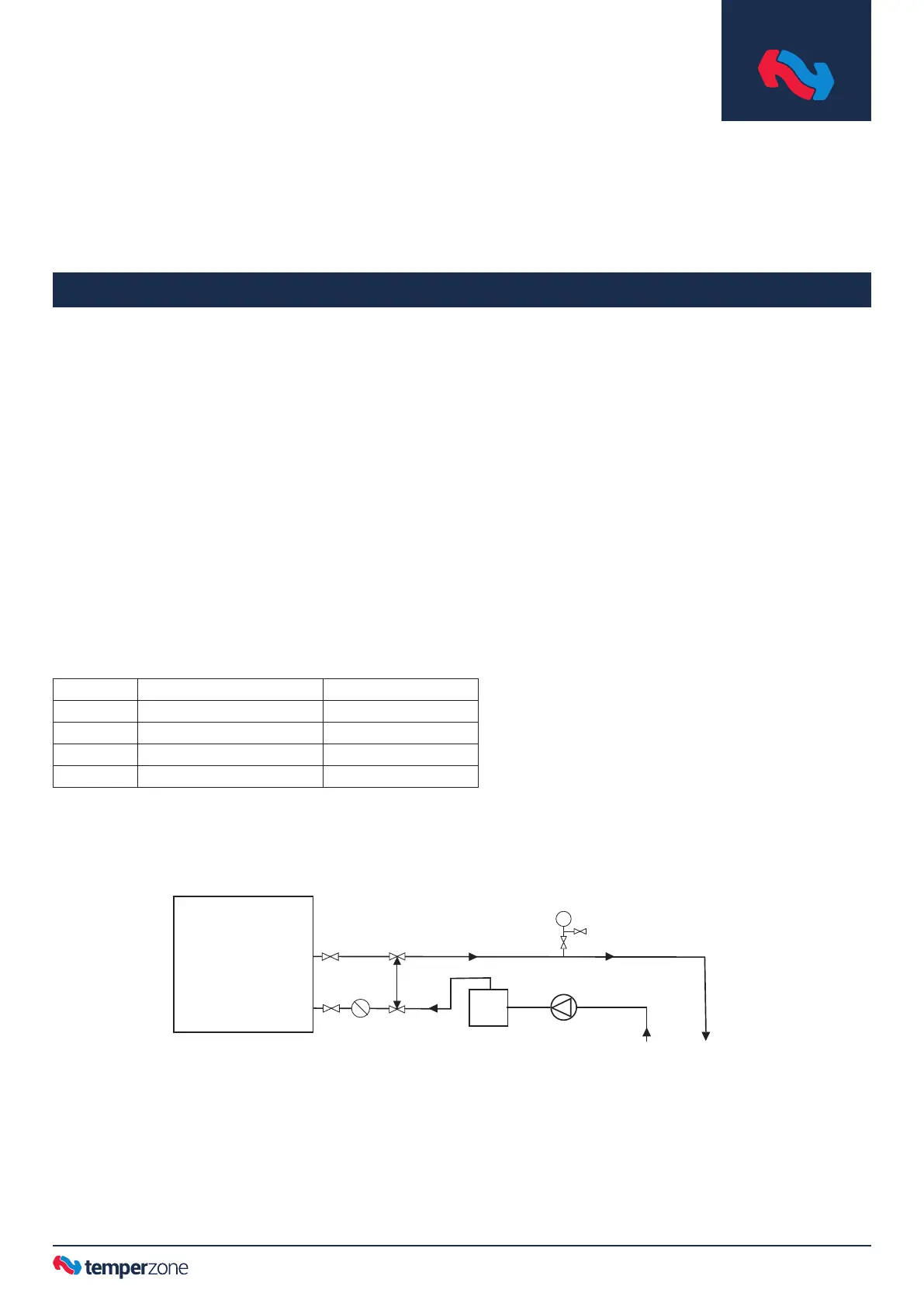
Figure 4 External Piping Schematic
– typical single unit installation
Note: Multiple units, installed in-series or in-parallel, may require
additional pumps to service the ow required.
Installation
MWP unit
Pressure PVC piping
Single MWP Heat Pump Piping
3 way
valve
Flow
Switch
Filter
Chlorinator
device
Return
from
Pool
Supply
to Pool
Pool
pump
3 way
valve
 Loading...