Page 16 of 24
Heat Pump Water Heaters
MWP Series
A Commissioning Checklist is included on the back page to
assist you with the commissioning process.
Power
WARNING! Do not turn the unit on until the external water pump
is switched on and water is owing through the unit.
a. Check the units are electrically connected in accordance
with the wiring diagram (refer Specications Sheet or unit
label).
b. Check all wiring connection and terminal tightness.
c. Check the dip switch settings on the TZT-100 and UC8
controllers match those on the MWP wiring diagram.
d. Remove the shipping blocks from beneath each compressor.
Check that each compressor is securely mounted.
e. Ensure the Temperature Controller (thermostat) is OFF.
f. Switch ON the Mains distribution board circuit breaker, the
internal circuit breakers and the unit’s external ON/OFF
switch.
g. Check the supply voltage.
h. Check the communications cable and sensor wire are
installed away from any power cables to avoid the possibility
of electrical interference.
i. Once started, check for correct rotation of the compressor. If
rotation is incorrect the compressor will not pump, be noisy
and draw low current. To correct motor rotation, swap two
phases at the mains power terminals.
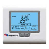
TZT-100 Quick Start Guide
1. Power on the MWP unit at the isolator switch.
2. Push TZT-100 Power button.
3. Push [mode] button and select ‘Heating’.
The MWP unit will operate continuously, rst to reach then
maintain the target temperature, provided the circulation/
ltration pump is operating 24/7. The default target water
temperature suitable for a pool is 28°C (Note, it will take up to 60
hours from cold state to reach and comfortably maintain
temperature – depending on the outdoor ambient and ground
temperatures).
The compressor should start, and after a few seconds the fan
should also start. If not, refer Troubleshooting section.
Refer TZT-100 Operation instructions for more detail (p.20).
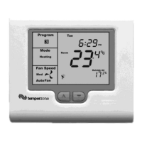
TZT-100 Advanced Installer Settings
Advanced Set-up will depend on the control method being
implemented (refer page 10) . A separate ‘Installer manual’ is
supplied with the TZT-100 covering advanced installation and
operation instructions.
Use following instructions for setting up the TZT-100 for the
type of operation required. There are a few factory settings that
must remain unchanged, regardless of the type of control
method to be used.
Dip switches 1, 2, 3, 5, 7 all set to OFF
position.
Dip switch 4 set to ON position.
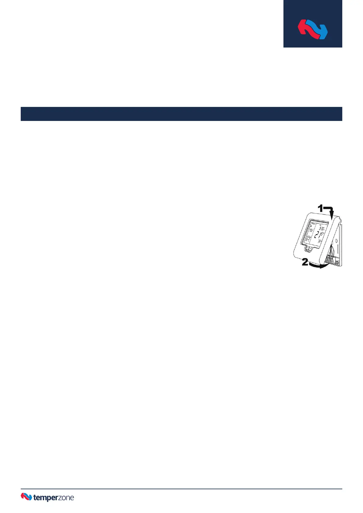
Dip switches can be viewed by separating
the front interface from the back panel
using a at head screw driver in the base
slot.
1. TZT-100 dip switches 6 & 8, to be set as required, according
to the chosen control method (refer page 10).
2. Enter the Installer menu:-
Press and hold O/RIDE button until the gures ‘88:15’
appears on the display (after about 15 seconds). Adjust this
gure to ‘88:21’ by pressing the up (▲) or down (▼) buttons,
then tap O/RIDE again to enter the menu.
Using the Installer menu, tap O/RIDE button to move forward
through the menu, tap PROG button to move backward
through the menu. Press up (▲) or down (▼) button to
adjust the value of each function.
3. Set the highest water temperature the user is permitted to
set the heat pump to run up to, as follows:-
Move through the Installer menu until HL=35 (default)
appears in the display. Press up (▲) or down (▼) button to
adjust the value in the range: 22°C — 28°C for a typical pool.
4. Check the setting of the T-T terminals that the water
temperature sensor is connected to:-
Move through the Installer menu until ‘tt=RS’ (default)
appears in the display. The default setting is correct for this
application. If the factory default is not showing then scroll
up (▲) or down (▼) until ‘RS’ appears.
5. Check the calibration of the water temperature sensor:-
Move through the Installer menu until the function ‘C1=3.0’
(factory default) appears on the display. If not, adjust ‘0.0’
by pressing the down (▼) button in 0.1 increments.
6. Exit the Installer menu by pressing PROG button.
Commissioning
 Loading...