Install the following ceramic disc capacitors. ** Be sure NOT to
use any of the .01 μF mylar capacitors required for C20-C27:
3-17 Capacitor C2, 33 μF.
3-18. Capacitor C1, 100 pF (marked 101).
3-19. Capacitor C18, 220 pF (marked 221).
3-20. Capacitor C4, .01 μF (marked 103) **
3-21. Capacitor C6, also .01 μF. **
3-22. Capacitor C7, also .01 μF. **
3-24. Capacitor C3, also .01 μF. **
3-25. Capacitor C8, .1 μF (marked 104).
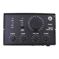
3-26. Install RF Gain control, 10K potentiometer R1, seating
the control squarely on the board before soldering. This is
important to assure a good fit to the aluminum subpanel.
3-27. Install Regeneration Control R5 per Step 3-26.
3-28. Install Fine Tuning Control R21 per Step 3-26.
3-29. Coaxial Cable Preparation:
A.
B.
C.
D.
Strip 1/2" of the outer black insulation from each end
of the RG 174 mini coax cable.
Gently unravel the exposed braids and twist the
strands to form single stranded conductors.
C. Strip 1/8" of the inner insulation from the center
conductor at each end.
Lightly tin the exposed braids and center conductors.
3-30. Solder one end of the cable prepared in 3-29 to the
ANTENNA points near the RF Gain control: the center conductor
is soldered to the "IN" pad, and the braid is soldered to GND.
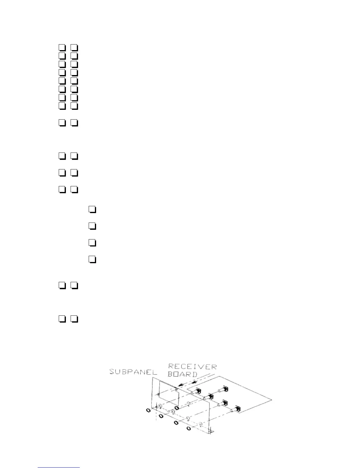
3-31. Gently slip the subpanel over the shafts and bushings
of the four board-mounted controls until it is flush against the
fronts of the controls. Notice how the locking pins should fit into
the small holes of the subpanel. (Do NOT mount washers and
nuts yet.)
1253 - 24
3-32. Notice how the bottom lip of the subpanel covers the
first half-inch or so of the entire front of the board' Remove the
subpanel, because NOW is the time to check this front area of
the board for:
Correct parts selection
Solder joint touchup
Wires properly trimmed to prevent shorting
Solder bridges
Correct soldering of controls so their locking pins
fit the corresponding holes of the subpanel
No loose strands of coax braid shorting to other
points on the board
3-33. At this point, you have installed all regeneration circuit
parts except L10 and C43. Before proceeding, please study
"Detail 3-44: Note on L10 and C43" at the end of this section.
3-34. Capacitor C43 installed not installed Per 3-44.
3-35. Inductor L10 installed not installed date_________
3-36. After performing all inspections of the front area of the
board explained in Step 3-32, mount the subpanel to the board
using a washer and 5/8" nut for each control.
3-37. Mount the Main Tuning control (R20) in its position on
the subpanel using the remaining washer and nut.
3-38. Prepare three 4.0" lengths of WHITE hookup wire,
referring to Step 1-27 as needed.
3-39. Solder one end of each of the three white wires to each
of the three lugs of the Main Tuning control.
3-40. Solder the wire from the lug nearest the large opening
for the bandswitch board to "R20A" on the board.
3-41. Solder the wire from the center (wiper) lug to R20B.
3-42. Solder the remaining wire to R20C.
3-43. Use any kind of tape to temporarily secure the antenna
coax to the subpanel during further assembly. It is important
that the solder connections not be stressed by repeated cable
movement.
1253 - 25