5-11. Set the main chassis/panel face down on a clean, non-
abrasive surface, and then lay the bandswitch board down inside
the front panel so that the two rows of LED's match their front
panel holes. Press gently so that all 9 LED bulb tips fit neatly
and uniformly into the holes.
5-12. Double-check correct anode orientation for each LED.
5-13. After making sure you have sufficient lighting for doing
soldering within the U-shape of the chassis/panel, start soldering
at least one lead of each LED. Start with the LED's easiest to
reach with your soldering tip and cut away excess leads frequently:
this will give you more working room.
5-14. Remove the board and set aside the chassis/panel.
5-15. Insert the pushbutton switch in its position on the front
of the board and solder all four pins to the pads on the front of
the board.
5-16. Double-check all work done in the preceding steps.
The switch board is now functional, requiring the following
hookup wire installations.
Prepare the following nine WHITE hookup wires and solder one
end of each wire to its position on the bandswitch board:
WIRE GROUP 1-5:
5-17. Band 1, 5.25 inches.
5-18. Band 2, 5.50 inches
5-19. Band 3, 5.75 inches
5-20. Band 4, 6.00 inches
5-21 . Band 5, 6.25 inches
WIRE GROUP 6-9:
5-22. Band 6, 5.50 inches
5-23. Band 7, 5.75 inches
5-24. Band 8, 6.00 inches
5-25. Band 9, 6.25 inches
5-26. READ FIRST: The bandswitch board is mounted in its
position on the FRONT SIDE of the subpanel using two 1/4" #4-
40 screws, #4 lock-washers and #4-40 hex nuts. DO NOT do a
"final" tightening, because the board will need to be adjusted as
the subpanel and main board assembly is mounted to the panel/
chassis. The screws are inserted from the back side of the
subpanel, through the board and secured by the washer and nut.
All wires pass through the large opening for soldering to the main
receiver board.
1253 - 34
5-27. Mount the bandswitch board on the front of the
subpanel as explained_in Step 5-26. Again, remember that a
"final" tightening is NOT done at this time.
5-28. Solder the 3" RED wire from "X" on the main board
(steps 4-4, 4-5) to "X" on the bandswitch board.
5-29. Prepare a 3" length of BLACK wire. solder one end to
"Y" on the main board and-the other end to "Y" on the band-
switch board.
5-30. Double-check all work done in steps 5-1 to 5-29.
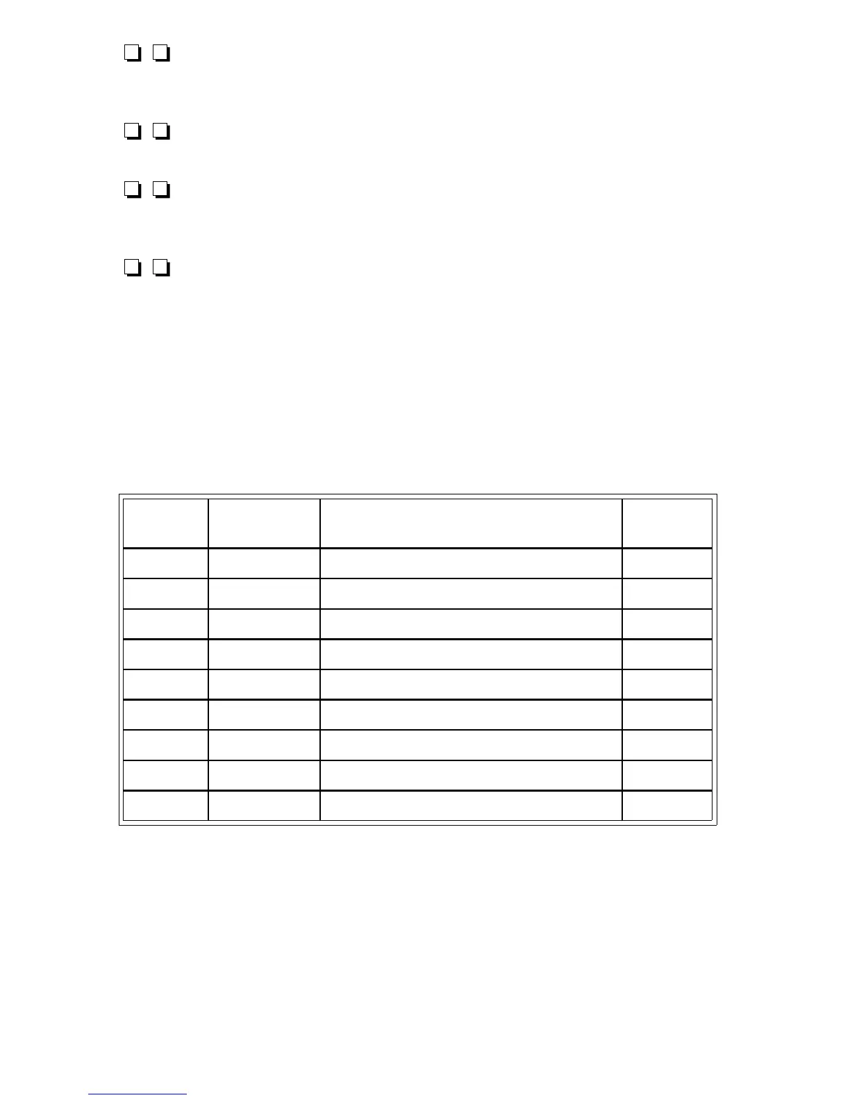
Chart 6.1: T-KIT Model 1253 Receiver
Bandswitching Quick-Reference Chart
Band Coil-Value Color Code Wire
Length
1 L1-68 μH blue-gray-black-gold 5.25"
2 L2-33 μH orange-orange-black-gold 5.50"
3 L3-12 μH brown-red-black-gold 5.75"
4 L4-8.2 μH gray-red-gold-gold 6.00"
5 L5-4.7 μH yellow-violet-gold-gold 6.25"
6 L6-3.3 μH orange-orange-gold-gold 5.50"
7 L7-2.2 μH red-red-gold-gold 5.75"
8 L8- 1.5 μH brown-green-gold-gold 6.00"
9 L9-1.2 μH brown-red-gold-gold * 6.25"
* or silver
1253 - 35