7-22. Adjust the board/subpanel assembly toward the front
panel so that the LED's fit neatly in their holes and that the
switch button works properly. While holding the subpanel firmly,
tighten the subpanel mounting screws. Then, tighten the rear
mounting screws of the receiver board.
7-23. Secure the 3" speaker with its mounting plate to the
top shell, using four (each) 3/8 #4-40 screws, #4 lock washers
and #4-40 hex screws.
7-24. Prepare a 9" length of WHITE hookup wire and solder
one end to the ( + ) lug of the speaker.
7-25. Prepare a 9" length of BLACK hookup wire and solder
one end to the ( - ) lug of the speaker.
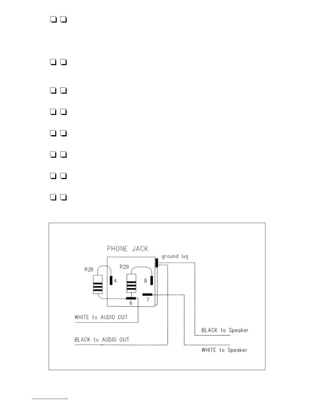
7-26. Referring to Figure 7.2 as needed, examine the
pattern of lugs on the back of the 1/4" phone jack.
7-27. Cut in half both wire leads of R28, 100 ohms (brown-
black-brown) and solder one end of R28 to lug 4 of the jack.
7-28. Cut in half both wire leads of R29, also 100 ohms and
solder one end of R29 to lug 8 of the jack.
7-29. Solder the remaining ends of R28 and R29 PLUS the
other end of the WHITE wire from "AUDIO OUT" to lug 6 of the
phone jack.
Figure 7.2
1253 - 42
7-30. The jack's ground lug is not numbered but is easily
recognized as an extension of the metal bracket on the outside of
the jack's body just above lug 2. Solder the two BLACK wires
from the speaker and the AUDIO OUT to this ground lug.
7-31. Solder the WHITE speaker wire to lug 7 of the jack.
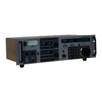
Figure 7.3
7-32. Referring to Figure
7.3, solder the RED wire
from ''Vcc Ext" to the ( + )
lug of the DC connector.
7-33. Referring to Figure
7.3, solder the BLACK wire
from "Vcc Ext" to the ( - ) lug
of the DC connector.
7-34. Mount the toggle switch on the front panel noting that
the locking tab in the smooth washer mates the small panel hole
beneath the switch hole. The smooth washer goes on the front
side of the panel. Be careful not to scratch the panel when
tightening the hex nut.
7-35. While the switch is a DPDT type, only an SPST
arrangement is used to turn the receiver on and off. (Later, you
may decide on a practical function for the unused pole, such as
grounding an antenna when the switch is in the "off " position.)
Solder one red wire from the "Power Switch" box on the board
to either of the BOTTOM switch lugs.
7-36. Solder the other red wire from “Power Switch” to the
switch lug immediately above the wire installed in step 7-35.
7-37. Slip a #10 solder lug over the shorter of the two #10
screws and pass the screw from within the chassis through the
GROUND hole of the rear panel. Then slip on a #10 lock washer
and a #10 hex nut. Tighten the nut all the way. Add two #10
flat washers and one #10 wing nut to complete the ground
terminal. for easier soldering, bend the solder lug away from
from the panel slightly, using a screwdriver or knife blade.
1253 - 43