7
• When you want to synchronise multiple 72-3555 generators or output 10MHz
reference frequency signal, use this internal output connector.
7. Air Vent
• To ensure the Generator does not overheat, keep this vent uncovered.
8. Fuse
• To prevent damage to the Generator, the fuse will blow and disconnect the power
supply if the input AC current exceeds 2A.
9. Master Power Switch
• To energize the Generator when set to “I”, otherwise set to “O” to disconnect AC
input (On/Off button on the front panel will not work).
AC POWER RECEPTACLE
AC power specication for the Generator: 100 to 240V, 45 to 440Hz, power fuse: 250V,
T2 A.
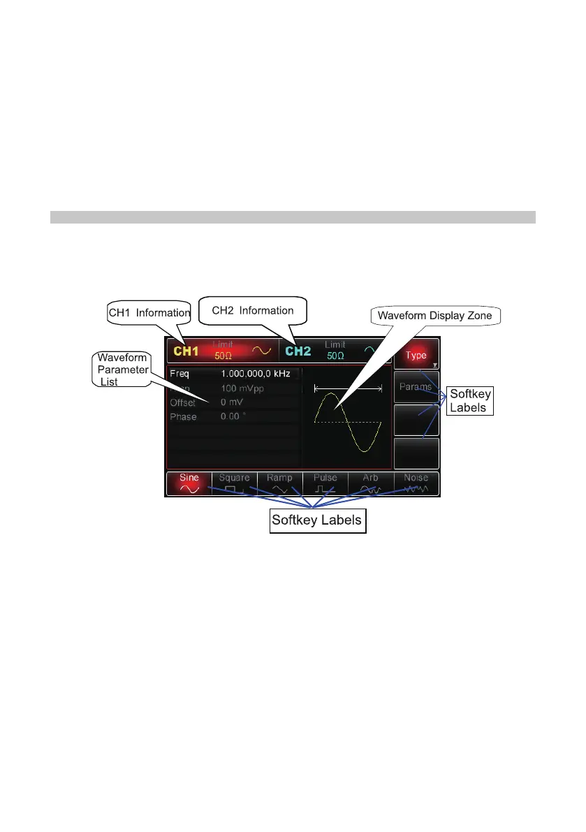
Display Interface
CH1 and CH2 information
• When the display is highlighted (red for CH1 and blue for CH2), it indicates which
channel information is enabled and which channel parameters can be set up.
• Only the highlighted channel can have its parameters changed.
• For the respective channels’ display there is a “Limit” icon that represents
the output amplitude limit. The limit will either be white or grey, for on and off
respectively.
• The impedance value of the output terminal needs to match (adjustable within
1Ω~10kΩ, or set to high impedance, 50Ω by default).
• On the right of the display it shows the current effective waveform (waveform
shape, or “Mod”, “Sweep” or “Impulse Train” icon) or “Off” in grey for when the CH
output connector is switched off.
Softkey Labels
• These labels identify the current functions of the functional menus softkeys and