EasyManua.ls Logo

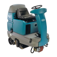
Tennant R14 User Manual

Tennant R14
58 pages
To Next Page IconTo Next Page
Page #1 background imageLoading...
Page #1 background image
Service Information Manual
R14
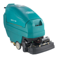
Dual Technology Rider Carpet Cleaner
Hygenic
R
Fully Cleanable Tanks
More than clean, it’s ReadySpace.
R
R
*1032129*
www.tennantco.com
1032129
Rev. 01 (12-2006)
North America

Questions and Answers:

Tennant R14 Specifications

General IconGeneral
BrandTennant
ModelR14
CategoryFloor Machine
LanguageEnglish

Summary

R14 Dual Technology Rider Carpet Cleaner

Control Panel Details

Details the location and function of controls on the machine's control panel.

Battery Compartment Area Details

Identifies components located within the machine's battery compartment.

Rear Machine Area Details

Locates components situated in the rear section of the machine.

Underside Details

Illustrates and labels components found on the underside of the machine.

Machine Specifications

Machine Specifications

Provides detailed technical specifications for the R14 carpet cleaner model.

Machine Dimensions

Details the physical length, width, and height of the R14 carpet cleaner.

Maintenance and Operation

Circuit Breakers and Fuses

Details the location, rating, and function of circuit breakers and fuses.

Battery Charging Procedures

Provides specifications and steps for safely charging the machine's batteries.

Routine Maintenance Tasks

Covers essential maintenance steps performed after each use and every 10 hours.

Periodic Maintenance Schedules

Details maintenance required at 80-hour intervals, including motor and battery upkeep.

Machine Handling and Systems

Instructions for priming, jacking, pushing, towing, and transporting the machine.

Storage and Recommended Items

Guidance on storing the machine and a list of recommended spare parts.

Electrical Systems and Diagnostics

Commonly Used Electrical Symbols and Terms

Defines electrical symbols and terms used throughout the manual.

Control Board 35 Pin Connector Detail

Provides a detailed breakdown of the 35-pin connector for the main control board.

Key OFF Power Distribution

Illustrates power distribution when the key is OFF and charger is disconnected.

Key ON, Operator on Seat Power Distribution

Shows power distribution when the key is ON and the operator is seated.

Operational Modes and Interlocks

Explains the machine's operational modes, entry sequences, indicators, and functions.

Diagnostic and Fault Alarms

Details alarm codes, sequences, and high current faults for diagnosing issues.

Related product manuals