KIT NO. 9014676- USA, 9014101- International
Page1of9
9014180 Rev. 03 (01- 2017) Tennant Company www.tennantco.com
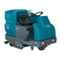
T300 IRIS Telemetry Kit
This kit includes the necessary parts to install IRIS telemetry technology on a standard T300 model.
INSTALLATION INSTRUCTIONS:
Installation Time: 1.5 Hours
Kit Installation Requirements:
- Tennant ServiceLink computer or a computer with Wi-Fi
connection to access the Tennant Service Application
Software, and USB cable (supplied with kit).
Computer System Requirements: Windows
7OS,
Microsoft .NET Framework 4.5 or later , USB Port.
- The IRIS Telemetry Kit MUST be activated to complete
installation. After kit is installed CALL Technical Support to
activate as described on page 6.
Spe c ia l Tools Requir e d: T-25 torque screwdriver
PREPARE MACHINE FOR KIT INSTALL:
1. Drain the solution and recovery tanks.
2. Park the machine on a level surface and remove key.
3. Disconnect battery cables from battery pack. If model
is equipped with the red quick disconnect connector ,
disconnect connector (Figure 1).
NOTE: If model is equipped with the optional battery
lift-out tray, the batteries and tray must be removed from
machine to allow space to replace the circuit board.
W ARNING: Always disconnect battery cables
from machine before working on electrical
components.
Models with battery
cable c onnectors
Fig. 1
4. Cut the three cable-ties that secure the vacuum hose,
drain hose, and battery cables to the heat- sink panel
(Figure 2).
Cable-Ties
Cable-Tie
Fig. 2
5. Remove the top two screws from the heat-sink panel
and carefully lower panel as shown (Figure 3). Place a
piece of cardboard over the battery terminals to prevent
contact with metal heat-sink panel.
FOR SAFETY: When servicing machine, keep all
metal objects off batteries.
Fig. 3
6. Disconnect wire connections and remove circuit board
from the heat-sink panel (Figure 4). The circuit board
is mounted to panel with eight torque head screws
and five standoffs. Squeeze standoff flange to release
circuit board from panel.
Standoff
Heat-sink
Panel
Fig. 4
