TENNEY ENVIRONMENTAL
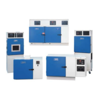
Tenney Junior Test Chambers: Models TJR and TUJR, W942, or WF4
Page 14
Making the Power Supply Connection to the Chamber:
A main power disconnect is not provided with your chamber. We recommend that a fused disconnect switch
on a separate branch circuit be installed as the power source to your chamber, in accordance with all
national and local electrical codes. Reference your Electrical, or Power Schematic for all electrical
requirements.
The power connection is made via a cord and plug for standard units. Connect the plug to a receptacle that
has the appropriate power supply on a branch circuit of its own. If the TempGard IV option is included,
refer to the “Alarm and Shutdown Circuit - TempGard IV” section for the connection procedure.
For special units that have the power supply hard-wired to the chamber, connect incoming lines to the main
input connections provided in the control section.
Warning! High Accessible Current – An Earth connection is essential before connecting the
power supply. Make sure equipment is properly grounded in accordance with all codes.
5.9 Application of Power
♦ Before energizing any equipment, make a visual inspection for loose components, electrical
connections, fittings, etc. Shut all operating switches to the “OFF” position before energizing.
♦ Have trained personnel start and check out the equipment before its first cycle.
Motor Rotation Check: Units with three phase motors must be checked to insure proper motor rotation. A
red arrow is located on the motor housing to show proper rotation. If it is opposite, shut down the oven and
disconnect the main power supply source. Perform Lock-Out / Tag-Out Procedures established by your
company. Reverse two of the line feeds to obtain proper operation. Failure to check motor rotation may result
in DAMAGE TO THE EQUIPMENT due to opposite airflow, or no airflow.
5.10 Operating With an Active Heat Load
Note: This feature is only available with the TempGard IV option.
When operating with an active heat load, such as introduced by a powered test unit, this heat must be
removed or the chamber temperature will rise. The internal logic of the controller will automatically turn on
the refrigeration system to maintain a set temperature. Although a cooling system failure is not likely to
occur, it is always a possibility when mechanical systems are used. In the event of a cooling system failure
that results in an out of limit over temperature condition, one or more of the system safeties will remove
power from the system. However, heating will continue if power remains applied to the active load. To guard
against this continued heating, the product should be powered through the spare contacts of the Master
Contactor (CON) from the TempGard IV circuitry. This is described in the Alarm And Shutdown Circuit
section.