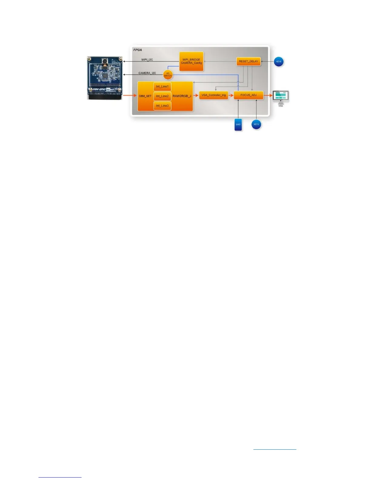
Figure 4-1 Block diagram of the digital camera D8M design with Line -Buffer
⚫ D8M_SET: This module is used to process D8M 640X480@60Hz raw data. It
includes three Line-Buffers that are used to store raw data, and two of the
Line-Buffers raw data will be extracted and converted to RGB data, the
Line-Buffer is also used to adjust the frequency difference between D8M and VGA.
⚫ VGA_Controller_trig: the VGA signal timing generator, can generate 640x480@60
Hz signal timing.
⚫ FOCUS_ADJ: This module provides two main functions. The first function is using
I2C bus to write D8M Voice Coil Motor (VCM) driver IC register, and control the
camera lens’ movements to perform image focusing. VCM driver IC register (I2C
Slave Address =0x18) shares I2C bus with camera module. The other function is
doing the current image high frequency component statistic. When the VCM
drives the camera lens’ movement, a real-time statistics of image high-frequency
sum will be done in every step of the moving. Finally, the lens will move to a
position which has the largest number of high frequency to complete the
automatic focus operation. Focus area can be selected by SW3. There are two
options:
o Select focusing the whole screen area (set SW3 to 0)
o Select focusing the middle area (set SW3 to 1).
Once you set SW3 to a value (0 or 1) and press KEY3 one time, the automatic focus
operation will be performed in the selected area.
⚫ FpsMonitor: This module will count D8M MIPI_PIXEL_VS signal pulses in 1
 Loading...