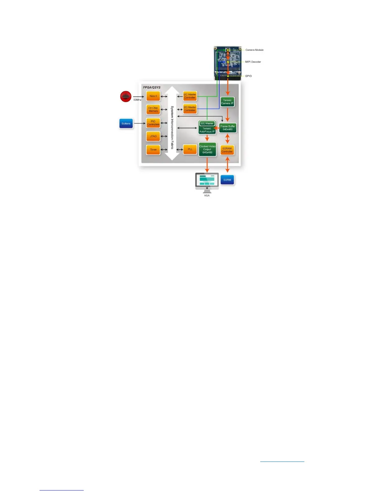
Figure 5-1 Function block diagram of DE1_SOC_D8M_VIP demonstration
The Nios II program running the on-chip memory controls the I2C controllers to
configure the image sensor, motor driver, and the MIPI Decoder IC. The first I2C
controller is used to configure the camera module, including the OV8865 image sensor
and the VM149C. The second I2C controller is used to configure the MIPI Decoder
TC358748XBG.
Note: The focus driver IC (VM149C) in the camera module is also configured by the
Terasic auto-focus IP through its own I2C master controller. Users must make sure
there is only one I2C master used one at a time.
◼ The default camera settings
In this demonstration, the default camera settings are:
⚫ Resolution: 600x480
⚫ Frame Rate: 60 fps
⚫ Pixel Data: RAW10
⚫ Bin Mode: 1, 2, 4 (achieved ZOOM-IN/ ZOOM-OUT function)
Users can change the settings base on their requirements.
◼ Design Tools
 Loading...