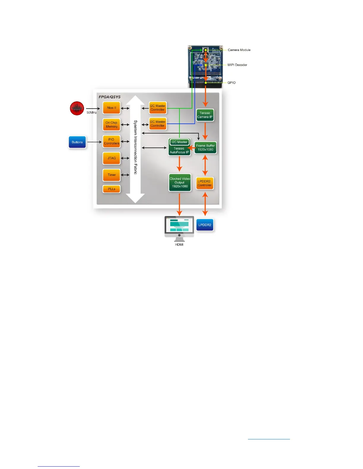
Figure 5-9 Function block diagram of C5G_D8M_VIP demonstration
C5G_D8M_VIP reference design is developed based on Altera’s Video and Image
Processing (VIP) suite. The Terasic Camera IP translates the parallel Bayer pattern
data into RGB data to meet the specification of the Altera VIP video streaming. The
Frame Buffer from the VIP is used for buffering image data in DDR3 and matching the
frame rate from the Terasic camera IP to the Clock Video Output of the VIP. It displays
the final 640x480 RGB frame image on the HDMI monitor. The auto-focus IP by Terasic
can be used to get a better image quality by finding the optimized focus setting.
The Nios II program running the on-chip memory controls the two I2C controllers to
configure the image sensor, motor driver, and the MIPI Decoder IC. The first I2C
controller is used to configure the camera module, including the OV8865 image sensor
and the VM149C. The second I2C controller is used to configure the MIPI Decoder
TC358748XBG.
Note: The focus driver IC (VM149C) in the camera module is also configured by the
 Loading...