August 2016Section 4 • Repair Procedures
4 - 6 AL4 • AL4000 Part No. 218567
WINCH
I
t
z
x y
aa
ab
a b c d e d f g h
j
k
lm
no
p
q
r
s
w
v u
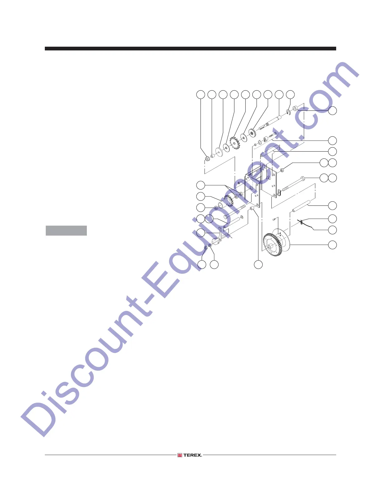
How to Assemble the Winch
1 Clean and inspect the winch components
before installing.
2 Install the pinion shaft bushings. Use a soft
metal drift equal to the outside diameter of the
bushing and tap with a rubber mallet until fully
seated.
3 Apply a small amount of lithium grease to the
large threaded section of the pinion shaft.
4 Insert the pinion shaft through the small
bushing in the winch frame, the pinion gear,
friction disc ratchet gear, friction disc, pinion
plate, spacer and fi nally through the large
bushing at the other side of the frame. Refer to
the illustration below.
Component damage hazard.
Grease or oil on the friction
disc will result in poor winch
performance. Do not allow grease
or oil onto the friction disk.
5 Install the retaining ring into the small groove at
the non-threaded end of the pinion shaft.
6 Install the ratchet pawl kit as shown in the
illustration. Securely tighten the fasteners.
7 Insert the drum bolt through the drum bolt
lock, winch frame, drum spacer, cable drum,
frame, lock arm spacer, lock arm and lock
arm bushing. Install and securely tighten the
locknut.
8 Working from the threaded end of the pinion
shaft, turn the shaft in a clockwise direction
until the retaining ring, installed in step 5, is
against the winch frame.
a pinion shaft bushing - large
b spacer
c pinion plate
d friction disc
e ratchet gear
f pinion gear
g pinion shaft
h retaining ring
i pinion shaft bushing - small
j ratchet pawl kit
k frame spacer
l frame spacer nut
m frame spacer bolt
n drum bolt
o drum bolt lock
p drum spacer
q cable fasteners
r cable
s cable drum
t lock arm spacer
u lock arm bushing
v lock arm nut
w lock arm
x cable roller
y cable roller washer
z winch lock gear nut
aa winch lock gear
ab pinion shaft nuts