9001-8
88
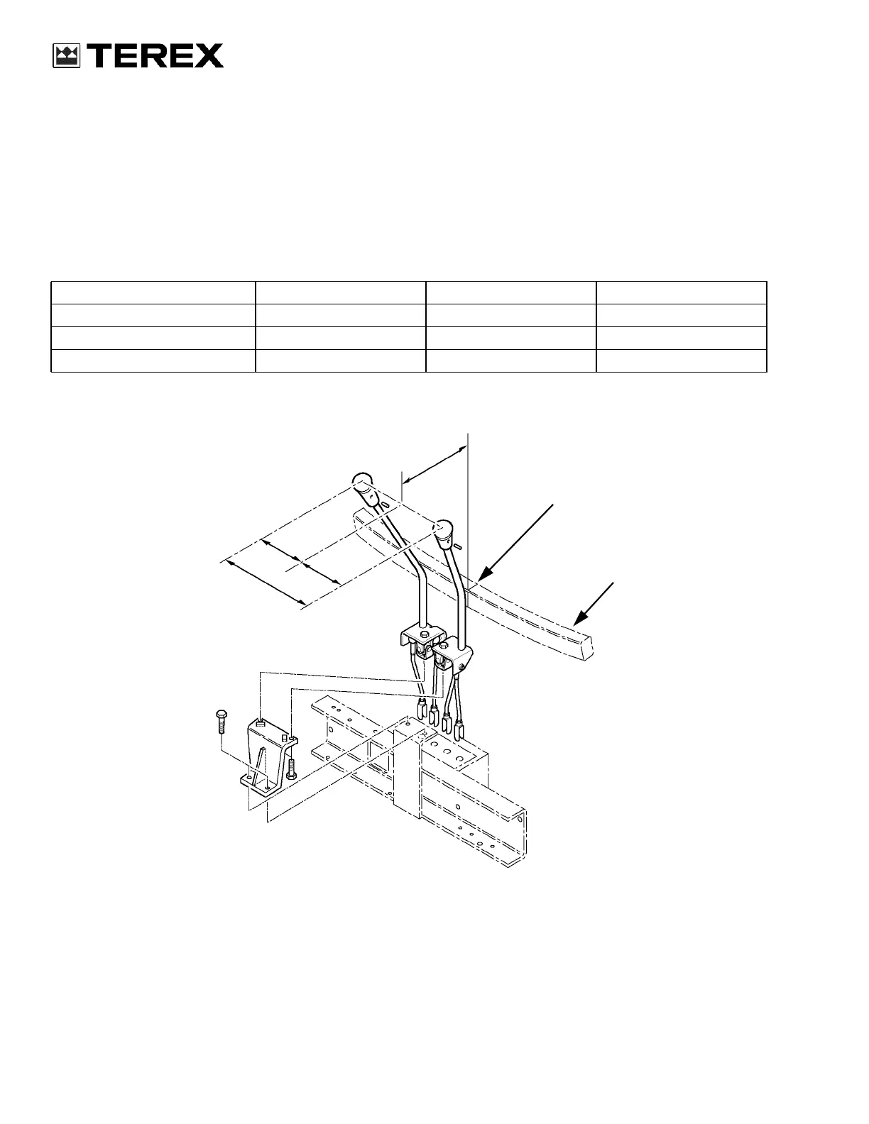
BACKHOE CONTROL LEVER ADJUSTMENT
Adjustment procedure
1. Park the machine on a level surface.
2. Switch off the engine.
3. Check that the distance from the cab frame to the
top of the backoe control levers corresponds to
A.
4. Check that the distance between the top of each
backhoe control lever and the centre line of the
machine corresponds to B.
5. Adjust the control rods at the backhoe valve
assembly until the distances are correct.
Standard SAE version
Version A B C
Standard mm (in)10 in (254mm) 5.65 in (143.5mm) 11.3 in (287mm)
I.S.O. mm (in)10 in (254mm) 5.65 in (143.5mm) 11.3 in (287mm)
X Pattern mm (in)9.88 in (251mm) 6.04 in (153.5mm) 12.08 in (307mm)
A
B
B
C
CENTER-LINE
OF MACHINE
CAB FRAME
REF
 Loading...