Do you have a question about the Terex Genie S-80 and is the answer not in the manual?
Key safety and operational instructions for machine maintenance.
Information on accuracy, product improvements, and submitting feedback.
Instructions on locating service, maintenance, and operator manuals.
Explains the format and meaning of machine serial numbers.
Guidelines for personal safety while working on or around the machine.
Guidelines for maintaining a safe work environment and practices.
Details on tires, wheels, lugs, and fluid capacities.
Data on drive speed, braking distance, and boom function speeds.
Requirements and types of hydraulic fluids, including optional fluids.
Specifications for drive, charge, function, and auxiliary pumps.
Specifications for Deutz, Perkins, and GM engines.
Overview of the repair procedures section and its scope.
Explanation of symbols used in repair procedures for clarity and safety.
Details on the ALC-500 circuit board and its replacement.
Joystick calibration and adjustment procedures.
Procedure for removing the platform from the machine.
Procedures for removing and bleeding the platform leveling slave cylinder.
Procedures for removing and bleeding the platform rotator.
Procedure for calibrating the platform overload system.
Procedure for repairing and removing the boom cable track.
Procedure for removing the boom lift cylinder.
Procedure for removing the boom extension cylinder.
Procedure for adjusting boom extend/retract cables.
Procedure for adjusting engine RPM.
Procedures for removing and installing the flex plate.
Specifications for Deutz, Perkins, and GM engines.
Component identification and torque specifications for the function manifold.
Procedures for adjusting relief valves on the function manifold.
Component identification for the 2WD and 4WD traction manifolds.
Procedures for testing valve coils and their resistance specifications.
Procedures for retrieving and understanding control system fault codes.
How to retrieve and interpret engine fault codes for Deutz and Perkins.
List of fault codes specific to the Deutz D 2.9 L4 engine.
List of fault codes specific to the Perkins 404F-22 engine.
Wiring diagrams for the machine's electrical systems.
Diagrams of the machine's hydraulic circuits.
Key to understanding electrical symbols used in schematics.
Key to understanding hydraulic symbols used in schematics.
Mapping of pin numbers to circuit numbers for various connectors.
Wiring diagram for the S-80X ground control box.
Electrical schematic for S-80X with Deutz TD2.9 L4 engines (ANSI/CSA).
Electrical schematic for S-80/S-85 with GM 3.0L engines (CE).
Hydraulic schematic for 2WD models.
Hydraulic schematic for 4WD models.
| Brand | Terex |
|---|---|
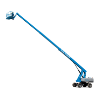
| Model | Genie S-80 |
| Category | Boom Lifts |
| Language | English |