Care and Maintenance 7
89/112TL160
Operating Manual 12.9.08 Version 1.0
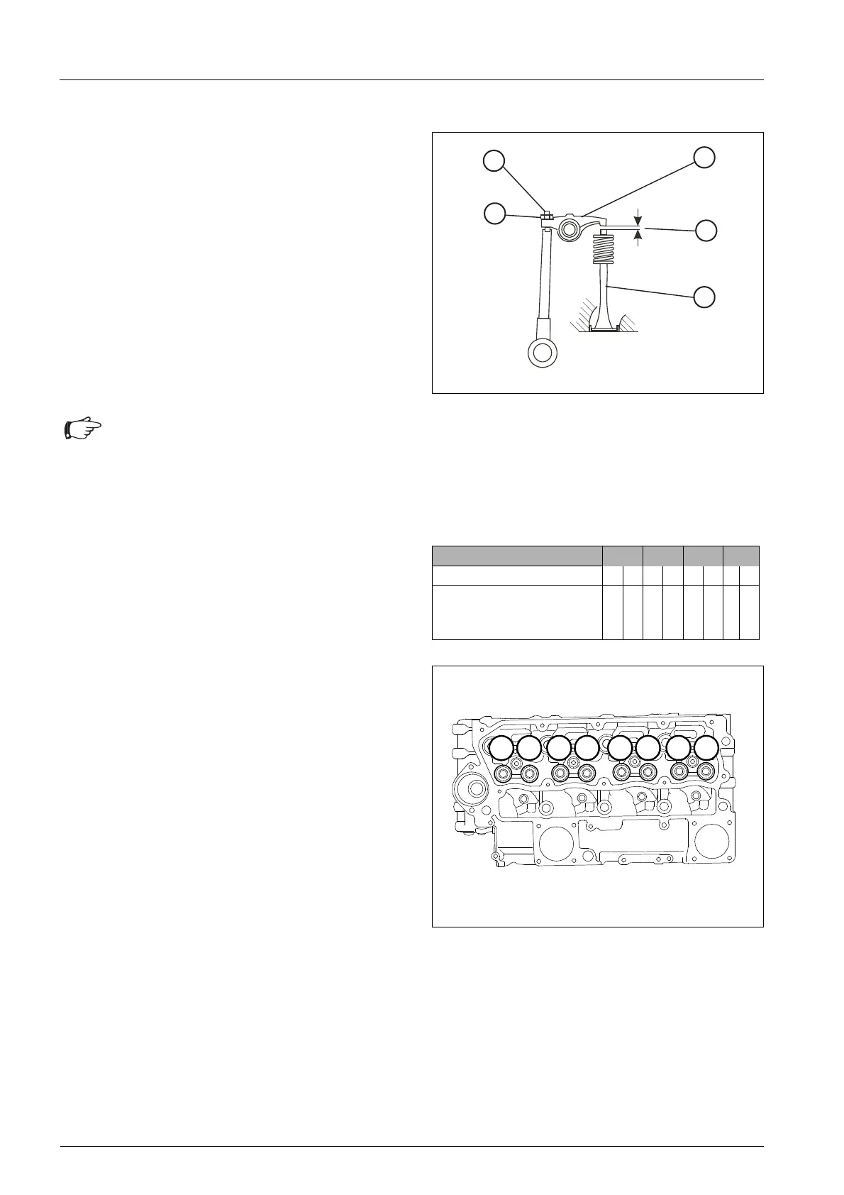
7.8.8 Checking the valve lash
• Test the valve lash (60/1) on a cold engine by
placing a feeler gauge between the upper part of
the tappet (60/3) and the rocker arm (60/2).
If necessary, adjust the valve lash as follows:
• Slacken counternut (60/4).
• Using a screwdriver, adjust the setting screw
(60/5) in such a way that the correct valve lash
(60/1) is obtained after the lock nut is tightened.
• Re-tighten counternut.
Valve adjustment
• Remove the cylinder head cover.
• Turn the crankshaft in normal direction of rotation
until the inlet valve 61/7 of cylinder no.4 begins to
open; the outlet valve 61/8 of the same cylinder is
not yet closed completely.
• Check the valve lash of valves 61/1 and 61/2 of
cylinder no. 1 and adjust if required.
• Adjust the valves 61/3 and 61/4 of cylinder no. 2,
as described above for the valves of cylinder no. 4,
for overlap.
• Then check the valve lash of valves 61/5 and 61/6
of cylinder no. 3 and adjust if required.
• Adjust the valves 61/1 and 61/2 of cylinder no. 1
for overlap.
• Check the valve lash of valves 61/7 and 61/8 of
cylinder no. 4 and adjust if required.
• Adjust the valves 61/5 and 61/6 of cylinder no. 3
for overlap.
• Check the valve lash of valves 61/3 and 61/4 of
cylinder no. 2 and adjust if required.
• Re-mount the cylinder head cover along with a
new gasket.
Fig. 60 Adjusting the valve lash
The correct valve lash is as follows:
Inlet valve = 0.20 mm
Outlet valve = 0.45 mm
Attention
The 1st cylinder is located at the front on the
fan side of the engine.
Cylinder no. 1 2 3 4
Valve no. 1 2 3 4 5 6 7 8
Valve
I = inlet
O = outlet
I O I O I O I O
Tab. 30 Cylinder and valve numbers
Fig. 61 Valve adjustment
 Loading...