4. Installation 17
4.5 Additions and Variations to the Typical System
This section shows variations and additions to the Typical ER3000 control
system shown in Figure 3. Alternatively, use Figure 2 as a baseline for systems
without an external transducer.
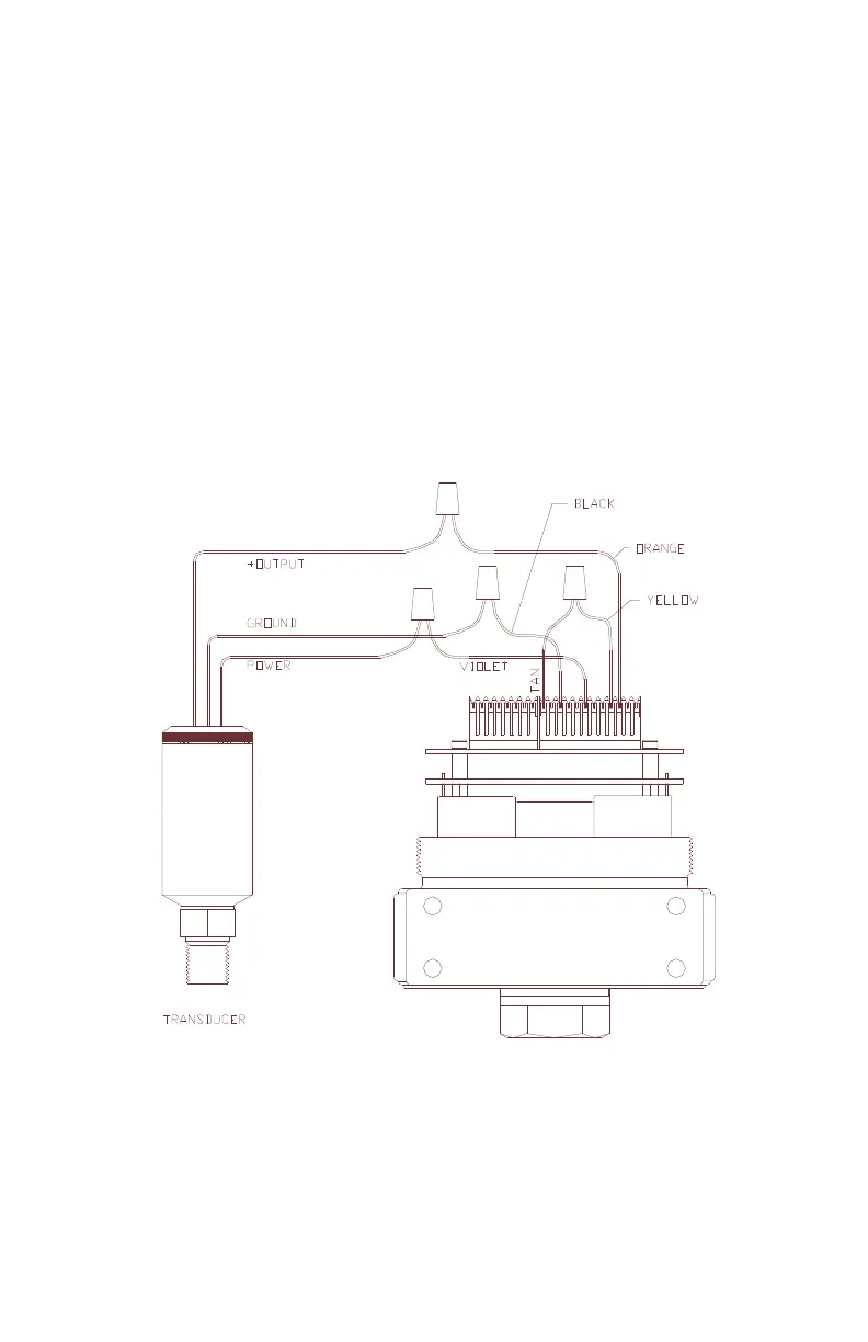
4.5.1 Transducer Wiring Configurations
The wiring for the two-wire transducer is shown in Figure 3.
The wiring for the three wire and four wire transducers are shown in Figure 4
and Figure 5 respectively. Connect the ER3000 to the transducer, or other
feedback source, as shown in the respective diagrams.
Check to ensure that the external feedback voltage/current select jumper, J5:2, is
installed for 4-20mAmp or removed for 1-5 Volt operation. There is no jumper
on the 0-10 Volt ER3000 models.
Figure 4: Three-Wire External Feedback Cabling
NOTE: Wire power as shown in figures 2 & 3