22 ER3000 User Manual
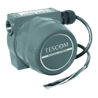
In order to avoid producing ground loops, it may be necessary in some systems
to monitor the voltage produced across the ER3000’s internal 250 Ω resistor
rather than breaking into the 4-20 mAmp loop.
Figure 12: Monitor voltage produced by 4-20 mAmp External Feedback
NOTE: Wire power as shown in figures 2 & 3
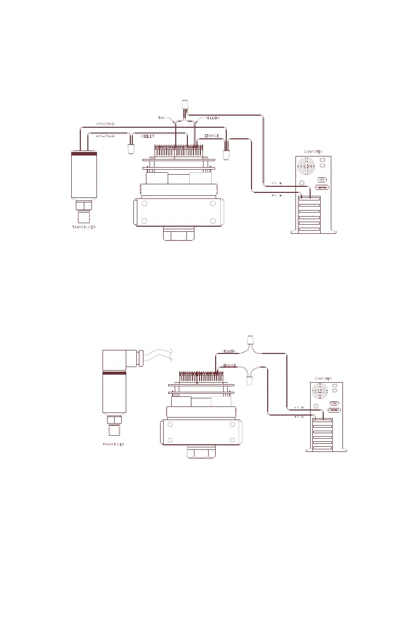
Figure 13: Monitor 1-5V/0-10V External Feedback
NOTE: Wire power as shown in figures 2 & 3
The wiring from the transducer is dependant on whether it is a 3-wire or 4-wire
transducer. Refer to Figure 4 and Figure 5 for 3-wire and 4-wire transducer
wiring schemes.