10
II. FRONT PANEL
2.1 Introduction
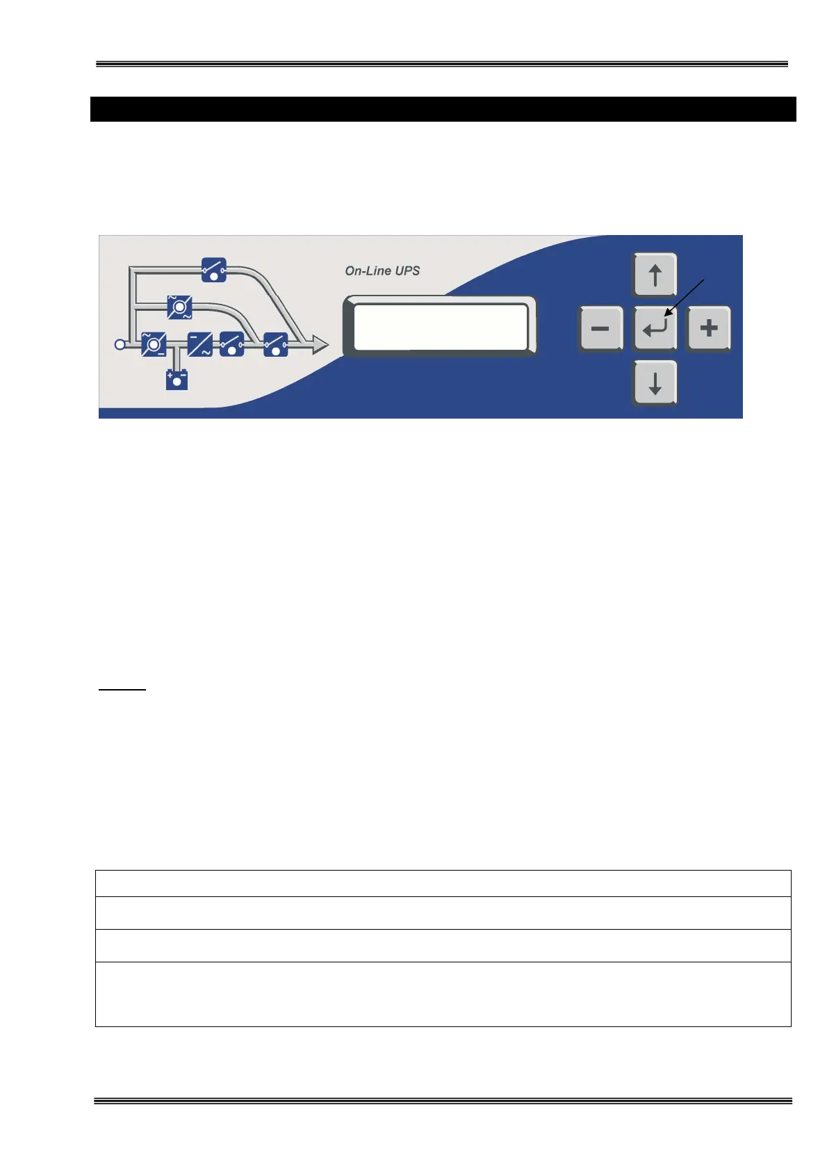
The front panel of UPS, consisting of a 2 lines alphanumeric display,6 status lamps,plus 5 function keys, allows
the complete monitoring of the UPS status. The mimic flow diagram helps to comprehend the operating status
of the UPS. By using the function keys operator can moves on menus and change some parameters.
Figure 2-1 Operator control and indicator panel
:
If lamp is lit mains is okay
:
If lamp is lit the rectifier is operating
:
If lamp is lit UPS is operating on batteries
:
If lamp is lit static bypass is active and load is connected to mains voltage
:
If lamp is lit mechanical bypass switch is on
:
If lamp is lit inverter feeds the load
: If lamp is lit S4 power output switch “1” on position. (Not exist in 40 kVA)
There are 5 function keys on front panel these are ENTER, UP, DOWN, PLUS and MINUS.
UP and DOWN keys help moving on menus, PLUS and MINUS keys select options, ENTER key means the
selected option or menu is valid.
NOTE : ALL MESSAGES SHOWN IN THIS CHAPTER IS VALID FOR MC VERSION OF UPS
CONTROL SOFTWARE.
2.2 Alarms And Status Messages
Totally 64 alarm and status messages are used in UPS which helps the user. Messages are coded for easy
dialog with service organization, all messages contains numbers A1-A2-A3….An. Messages and events in UPS
are recorded to a log file with event time and date
ALARM DESCRIPTION
Bypass system failure
1) Maybe bypass parts are defective call service
Inverter digital start system is failed
Internal failure. Call service.
Overload in UPS repeated at 3 times in 30 min.
1) Overload
2) Fan failure or durty air inlets,outlets
3) Bad UPS settling
L1
L2
L3
L4
L5
L6
L7