Do you have a question about the Tescom CL115D Series and is the answer not in the manual?
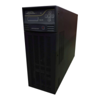
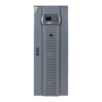
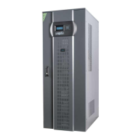
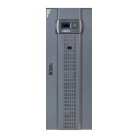
Detailed description of the functions and components of the CL115D UPS.
Explanation of mimic lamps on the control panel indicating bypass and inverter status.
Description of the 5 control keys used for navigating menus and confirming selections.
Overview of the 2-level menu structure for the LCD panel and status display.
Details on accessing and viewing measured parameters and UPS status in the Measures Menu.
Information on viewing recorded alarms, warnings, and faults with timestamps in the Alarms Menu.
Accessing system information such as firmware version, model, and battery status.
Overview of user-adjustable operating modes, options, and parameters.
Details on selectable options like operating mode, restart, remote control, and battery test.
Functionality to view and set the UPS's real-time clock (RTC) date and time.
Accessing maintenance information and service functions like hour meter and fault reset.
Applying immediate commands to the UPS, such as sound control, bypass, and lamp tests.
Table listing alarm and warning messages, their class, and descriptions.
Table listing fault codes, their messages, status, and troubleshooting steps.
Preliminary information and checks required before installing the UPS.
Information regarding the UPS's compliance with EMC standards and potential interference.
Guidelines for selecting a suitable site for UPS installation, considering environmental factors.
Instructions for safely unpacking the UPS unit from its packaging.
Steps to verify all included items are present after unpacking the UPS.
Important considerations and steps for physically installing the UPS unit.
Detailed instructions and diagrams for making electrical connections to the UPS.
Visual representations of basic and split bypass input connection configurations.
Specifications for input/output cable sizes and fuse ratings for the UPS.
Guidance on making power and grounding connections for the UPS unit.
Information on connecting alarm relay outputs and digital/REPO inputs.
Details on the RS232 connector, including hardware specs and dry contact relay outputs.
Explanation of the REPO (Remote Emergency Power Off) input and its function.
Step-by-step procedure for connecting input, output, and battery cables.
Overview of the UPS's purpose and how it provides constant power.
Details on various protection mechanisms within the UPS, including overload and battery protection.
Steps to perform before powering on the UPS for the first time.
Comprehensive guide for the initial power-up sequence of the UPS.
Procedure for turning on the UPS under normal operating conditions.
Steps to safely turn off the UPS while it is in normal operation.
How to manually transfer the load to the bypass supply without interruption.
Procedure for transferring the load to a maintenance bypass switch.
Description of the 2-line alphanumeric LCD display and its functions.
Explanation of mimic lamps on the control panel indicating bypass and inverter status.
Description of the 5 control keys used for navigating menus and confirming selections.
Overview of the 2-level menu structure for the LCD panel and status display.
Details on accessing and viewing measured parameters and UPS status in the Measures Menu.
Information on viewing recorded alarms, warnings, and faults with timestamps in the Alarms Menu.
Accessing system information such as firmware version, model, and battery status.
Overview of user-adjustable operating modes, options, and parameters.
Details on selectable options like operating mode, restart, remote control, and battery test.
Functionality to view and set the UPS's real-time clock (RTC) date and time.
Accessing maintenance information and service functions like hour meter and fault reset.
Applying immediate commands to the UPS, such as sound control, bypass, and lamp tests.
Table listing alarm and warning messages, their class, and descriptions.
Table listing fault codes, their messages, status, and troubleshooting steps.
Details on the standard RS232 serial communication interface for UPS units.
Information on the optional RS485 interface for long-distance communication.
Explanation of dry contact outputs for major event notifications.
Details on SNMP connection availability for network monitoring and management.
Information on Modbus connection for industrial communication protocols.
Measures to secure the UPS serial port against unauthorized access and commands.
Description of internal and external SNMP adaptors for network monitoring.
Specifications table detailing Model, Output VA/KW, and Power Factor.
Technical specifications related to UPS input voltage, frequency, and power factor.
Technical specifications for UPS output voltage, frequency, tolerance, and load.
Specifications concerning the number, type, voltage, and charging of the UPS batteries.
Details on available communication ports and interface options for the UPS.
Environmental operating conditions, installation altitude, and noise level specifications.