3
Cooling
A cooling fan is installed on the rear panel of the UPS as air outlet (see back view nr:12 item of the UPS) ,and
another cooling fan is installed on the front side of the UPS as air inlet (see front view nr:1 item of the UPS). A
temperature sensor on the controller board, measures the ambient temperature inside the cabinet and, if the
temperature is higher than a predetermined value,UPS produces an overtemperature alarm. The measured
cabinet inside temperature is also displayed on the panel and used for changing the battery-charging voltage to
compensate for the temperature changes.
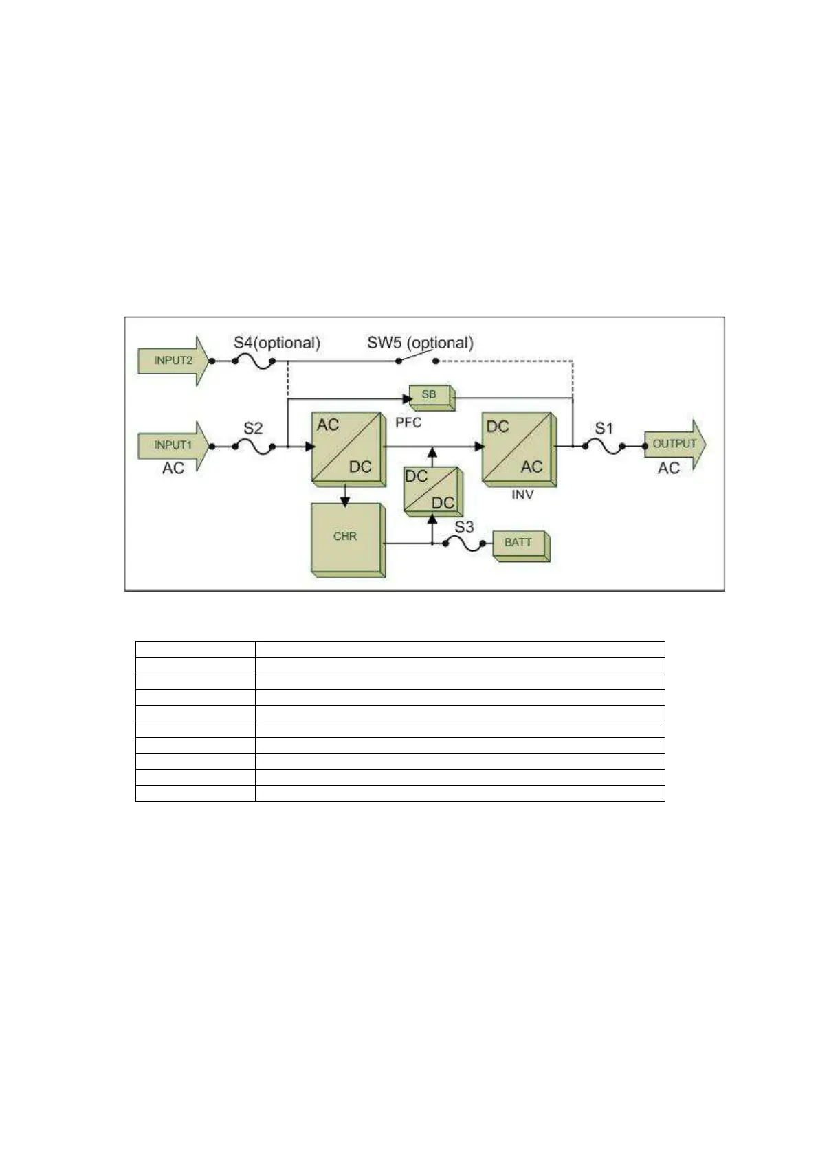
Block diagram of the UPS
All power stages and switches/fuses of a CL115D model UPS are shown on the above block diagram.
S1 Output switch/fuse
S2 Mains input switch/fuse
S3 Battery input switch/fuse
S4 Bypass input switch/fuse (OPTIONAL)
SW5 Maintenance bypass switch (OPTIONAL)
SB Static bypass block
PFC Input power factor correction block
CHR Battery charger block
INV Inverter block
BATT Battery group