11
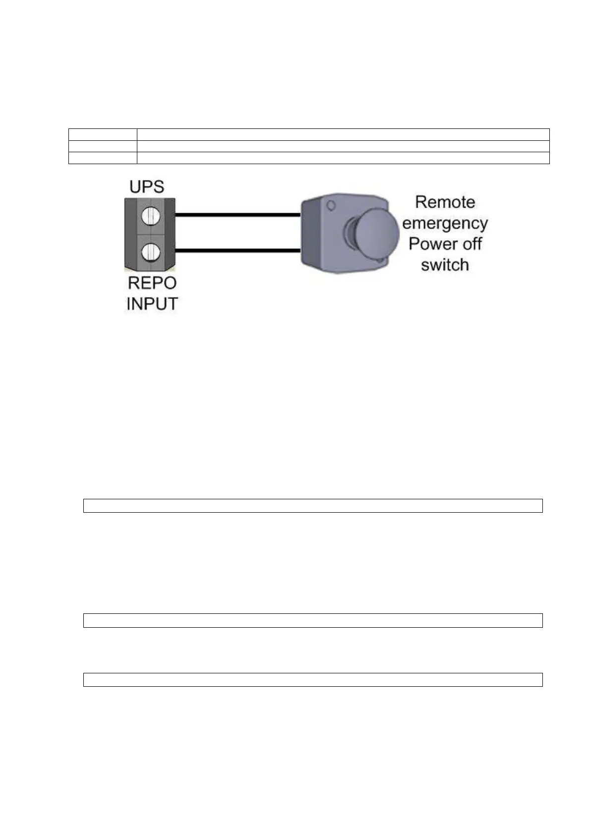
EXTERNAL REPO BUTTON
REPO input is the screw terminal pair at the rear next to the RS232 connector. The function of the REPO input
can be programmable from ADJUST MENU. The selectable options are:
Function Description
NO contact If REPO input terminals are shorted emergency power off will applied
NC contact If REPO input terminals are opened emergency power off will applied
This isolated input is used to turn off the UPS remotely in case of emergency.
The UPS is supplied from the factory with REPO terminals open-circuited ( see “View of the UPS connections”)
if those two (NO) terminals are shorted, UPS shuts-down the output voltage.
In case of emergency ,by activating the stop device, the UPS enters to stand-by mode and powers-off the load
completely.
The REPO circuit is self-powered ,no external power supply voltage is therefore required. If the external REPO
switch is pressed (at least 1 second) UPS turns off its output.
WIRING PROCEDURE
1.
Remove the metal guard on the input/output terminal group and connect phase ,neutral and earth input
cables. During connection match phase cable to phase input ,neutral cable to neutral input , earth cable to
earth input.
Input Power Connections
2.
For output connections you have three outlets at the back of the UPS
- Two IEC output sockets are available. You can directly plug the load cable into anyone of these outputs.
- If the output will be connected to the load distribution system directly, you can use screw terminal outputs.
During connection of the load, match phase cable to phase output, neutral cable to neutral output, earth
cable to earth output terminals.
Reassemble the metal guard removed previously.
Output Connections
3.
If external batteries are used , turn off the battery fuse and plug on the battery cable to the external battery
socket on the rear panel of the UPS.
External battery connection
4.
Also proper control and signal wire connections (alarm relays, REPO etc.) should be made through the
screw terminal block shown in figure 11.
Note :These auxiliary cables must be shielded and double insulated. (Recommended cross-section =1mm
2
)