Do you have a question about the Tesla Gen 3 and is the answer not in the manual?
Safety instructions concerning risks of fire and electric shock when using the product.
Lists essential warnings for safe operation, supervision, earthing, and handling of the Wall Connector.
Provides cautions regarding power sources, installation, temperature limits, and qualified personnel.
Details maximum current output (amps) and estimated power output for various grid connections.
Details conductor and earth wire sizing, multiple connectors, and outdoor installation requirements.
Explains earth path requirements, TT/IT grid support, and UK-specific PEN fault requirements.
Explains Wi-Fi communication with routers, vehicles, mobile devices, and other Tesla products.
Describes the Wall Connector's WPA2 password-secured Wi-Fi access point for commissioning.
Enables firmware updates, remote diagnostics, and data tracking via a local Wi-Fi network.
Details built-in RCD Type A + DC 6mA for AC and DC earth fault interruption.
Monitors earth connection and automatically recovers from faults; configurable options.
Explains automatic resume of charging after power restoration and manual resume option.
Automatic firmware updates improve user experience and introduce new features via Wi-Fi.
Monitors temperatures, reduces speed if hot, and displays error codes for high temperatures.
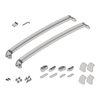
Lists essential tools for installation: torque driver, multimeter, stud finder, tape measure, drills.
Lists optional tools such as step bits and a computer with Wi-Fi for installation assistance.
Guides on selecting an installation location based on cable length and clearance for the unit.
Specifies maximum, recommended, and minimum indoor/outdoor installation heights.
Advises on placement to avoid obstructions and ensure optimal Wi-Fi connectivity.
Details the available wire entry locations: top, rear (left/right), and bottom entry paths.
Instructions for drilling holes, using templates, and attaching the wirebox to the mounting surface.
Guides on cutting wires to length, stripping ends, and routing them into the wirebox terminals.
Details stripping wire ends, inserting into terminals, torquing, and securing wires with zip ties.
Instructions on attaching the main unit to the wirebox and securing it with the provided fasteners.
Explains startup sequence and various LED light codes for different operational states.
Lists and explains various red blink error codes and their corresponding meanings.
Introduces UK regulations for EV chargers on TN-C-S (PME) supplies and code requirements.
Explains TN-C-S (PME) earthing and hazards of a broken PEN conductor in UK installations.
Lists relevant codes and standards like BS 7671, IET Code of Practice, and BS IEC EN 61851-1.
Details five options from BS7671:722.411.4.1 for earthing EV chargers on PME supplies.
Option for three-phase installations where voltage between main earthing terminal and Earth is low.
Option requiring connection to an earth electrode with specific resistance for safety.
Option using a device to disconnect the vehicle if voltage between protective conductor and Earth exceeds 70V.
Option for single-phase installations using a device to disconnect if voltage between line and neutral varies.
Option using an alternative device that provides equivalent safety to options (iii) or (iv).
Discusses EVSE requirements for protective earthing conductors, prohibiting switching within the charger.
Describes commercial stand-alone devices for compliance with option (iv) of Regulation 722.411.4.
Mentions electrical separation via isolating transformer or converting to TT earthing system.
Provides electrical separation between charger and installation using an isolating transformer.
Describes converting only the charger circuit to a TT system, with specific conditions.
Discusses converting the entire installation to a TT system, with recommendations and potential issues.
| Type | Wall Connector |
|---|---|
| Connectivity | Wi-Fi |
| Cable Length | 24 feet |
| Compatibility | All Tesla vehicles |
| Installation | Hardwired |
| Maximum Output | 11.5 kW |
| Connector Type | Tesla proprietary |
| Charging Speed | Up to 44 miles of range per hour |
| Amperage | 48A |
| Voltage | 240V |
| Power Output | 11.5 kW / 48A |