Electrical connection
8
Electrical connection
120V above ground
WARNING: Before commencing any electrical installation, always make sure that the
electricity supply has been isolated at the main circuit breaker panel. ▲
Note: The following connection details described here are primarily used in North America.
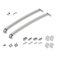
To access the electrical connections, open
the enclosure by removing the two screws
on the left-hand side using a T15 Torx L
driver. Then unhook the latch located on
the bottom of the unit (over the cable
holder).
Caution: Before connecting any
wires, make sure you have identified
the type of utility service connection
available. For more information, refer to
Utility service connections, page 4.
ClipperCreek, Inc.
READY
CHARGE
PROTECT
SERVICE
VEHICLE
GROUND
TERMINAL
L1
L2
GND
CONTACTOR
Service Side
Vehicle Side
Note:
• The Home Connector requires a
dedicated 208/240 VAC 60 Hz,
single-phase circuit, with its own 90A
circuit breaker.
• Do not use a GFCI breaker. The Home
Connector contains a Personal
Protection circuit specifically designed
for use with electric vehicles.
• Only 3 wires are required (L1, L2 and
GND), as shown in the illustration.
For branch circuits of 90A, use 4 AWG,
75°C copper wire. For installations less
than 90A, use conductors sized
according to Table 310.16 of NEC, or in
accordance with local electrical codes.
• The two phases (L1 and L2) are
terminated on the input side of the
CONTACTOR. The ground (GND) is
terminated on the Ground Terminal at
the bottom of the enclosure.
• Be careful not to damage the PC Board
when removing the power entry
knock-out, attaching the conduit, or
when wiring the service conductors to
the contactor.
Installation is complete. Before securing
the enclosure, perform the
post-installation testing procedure
described on page 10.
Home Connector Users Manual.book Page 8 Monday, April 26, 2010 12:38 PM
 Loading...