®
TV 450/455 Resistance of earth connection
35
measured resistance. The lead compensation is therefore a very important feature to
obtain correct result.
Each of R LOWΩ and CONTINUITY has own compensation.
symbol is displayed if
the compensation was carried out successfully.
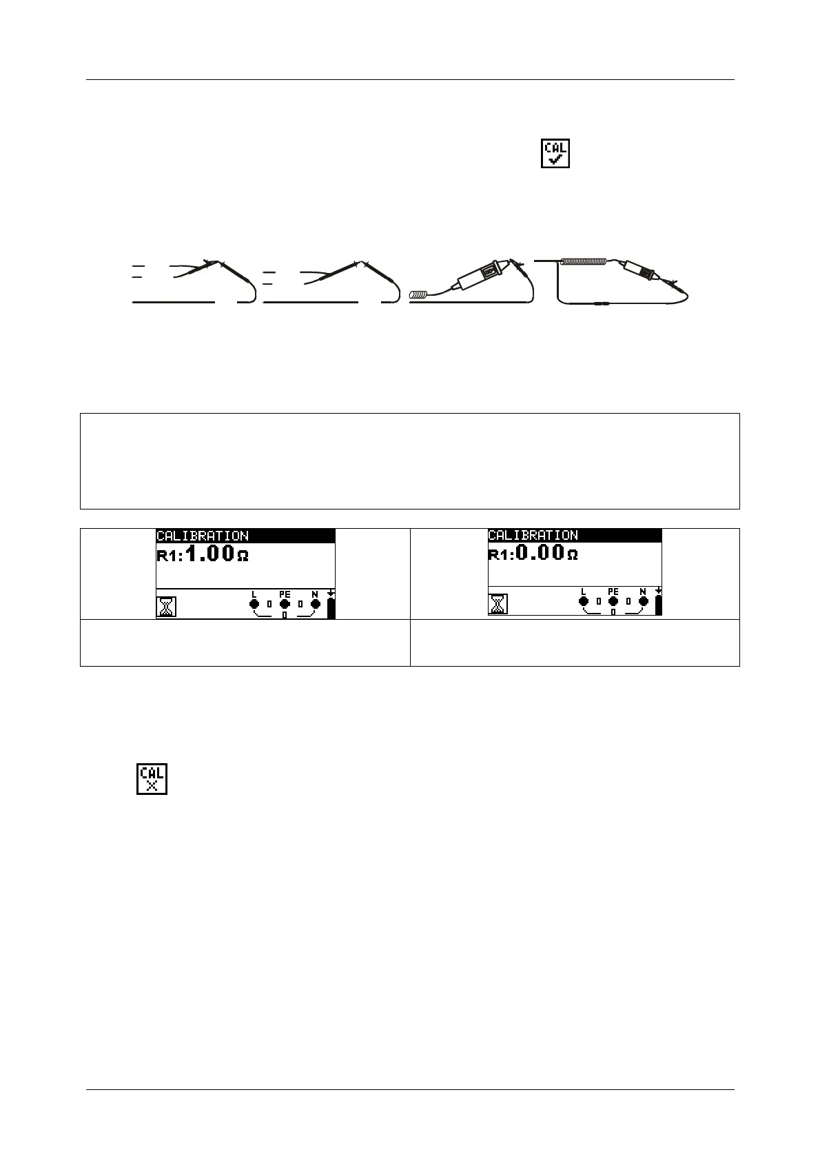
Circuits for compensating the resistance of test leads
N
/
L
2
L
/
L
1
L
/
L
1
P
E
/
L
3
N
/
L
2
P
E
/
L
3
rolongation lead
Figure 5.13: Shorted test leads
Compensation of test leads resistance procedure
Select R LOWΩ or CONTINUITY function.
Connect test cable to the instrument and short the test leads together (see figure
5.13).
Press TEST to perform resistance measurement.
Press the CAL key to compensate leads resistance.
Figure 5.14: Results with old calibration
values
Figure 5.15: Results with new calibration
values
Note:
The highest value for lead compensation is 5 Ω. If the resistance is higher the
compensation value is set back to default value.
is displayed if no calibration value is stored.