®
TV 450/455 Resistance of earth connection
34
5.3.2 Continuous resistance measurement with low current
In general, this function serves as standard Ω-meter with a low testing current. The
measurement is performed continuously without polarity reversal. The function can also
be applied for testing continuity of inductive components.
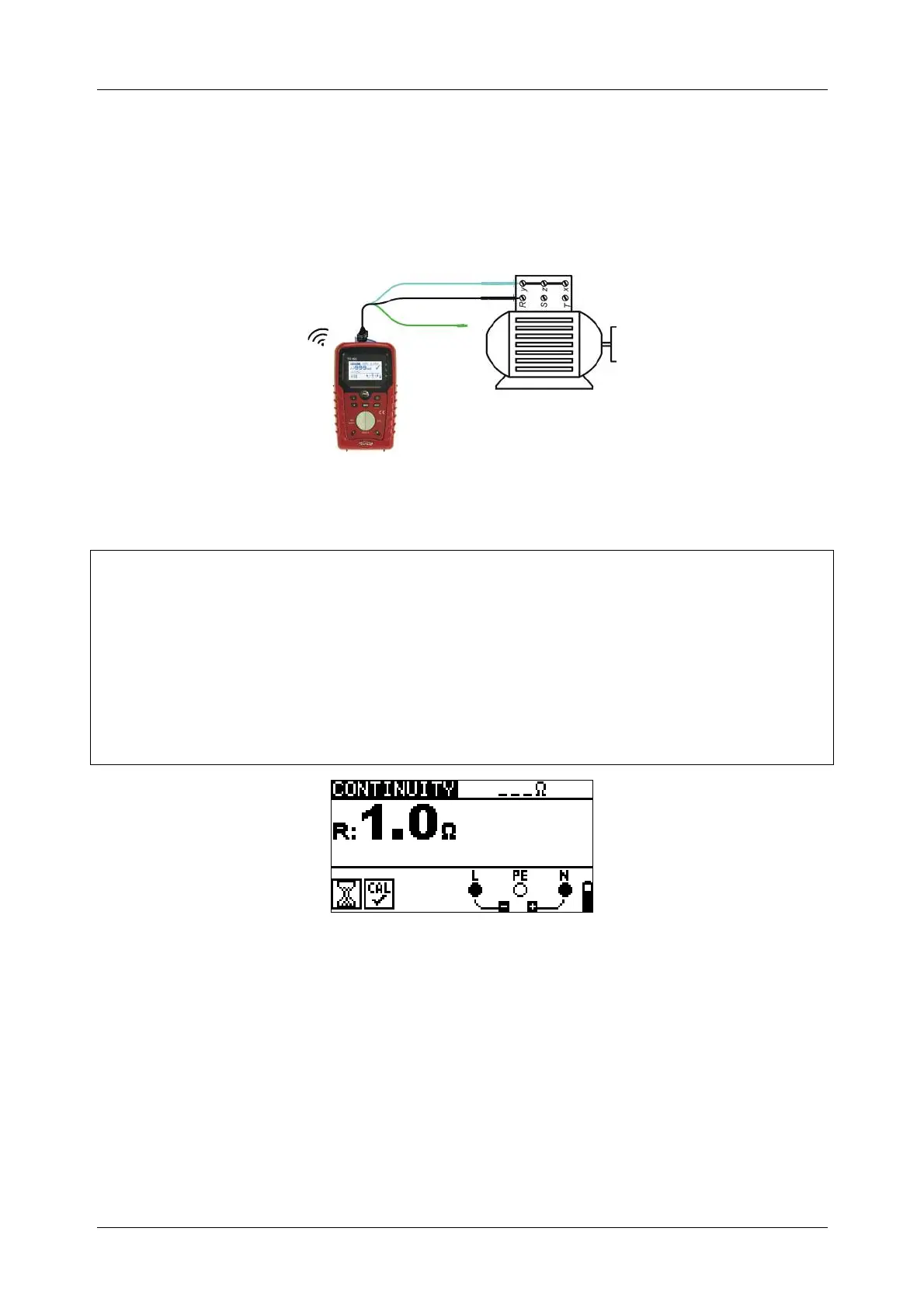
Test circuit for continuous resistance measurement
Figure 5.11: 3-wire test lead application
Continuous resistance measurement procedure
Select continuity function using the function selector switch.
Set sub-function CONTINUITY.
Enable and set the limit (optional).
Connect test cable to the instrument.
Compensate test leads resistance (if necessary, see section 5.3.3).
Disconnect from mains supply and discharge the object to be tested.
Connect test leads to the tested object (see figure 5.11).
Press the TEST key to begin performing a continuous measurement.
Press the TEST key to stop measurement.
After the measurement is finished, store the result.
Figure 5.12: Example of continuous resistance measurement
Displayed result:
R............Resistance
Note:
Continuous buzzer sound indicates that measured resistance is less than 2 Ω.
5.3.3 Compensation of test leads resistance
This chapter describes how to compensate the test leads resistance in both continuity
functions, R LOWΩ and CONTINUITY. Compensation is required to eliminate the
influence of test leads resistance and the internal resistances of the instrument on the