®
TV 450/455 Line impedance
48
Step 2: Measuring the voltage drop
Select the ΔU sub-function using the function selector switch and / keys.
Select test parameters (Fuse type must be selected).
Connect test cable or plug commander to the instrument.
Connect the test leads to the tested points (see figure 5.30).
Press the TEST key to perform the measurement.
Store the result by pressing the MEM key.
* model MI 3125B
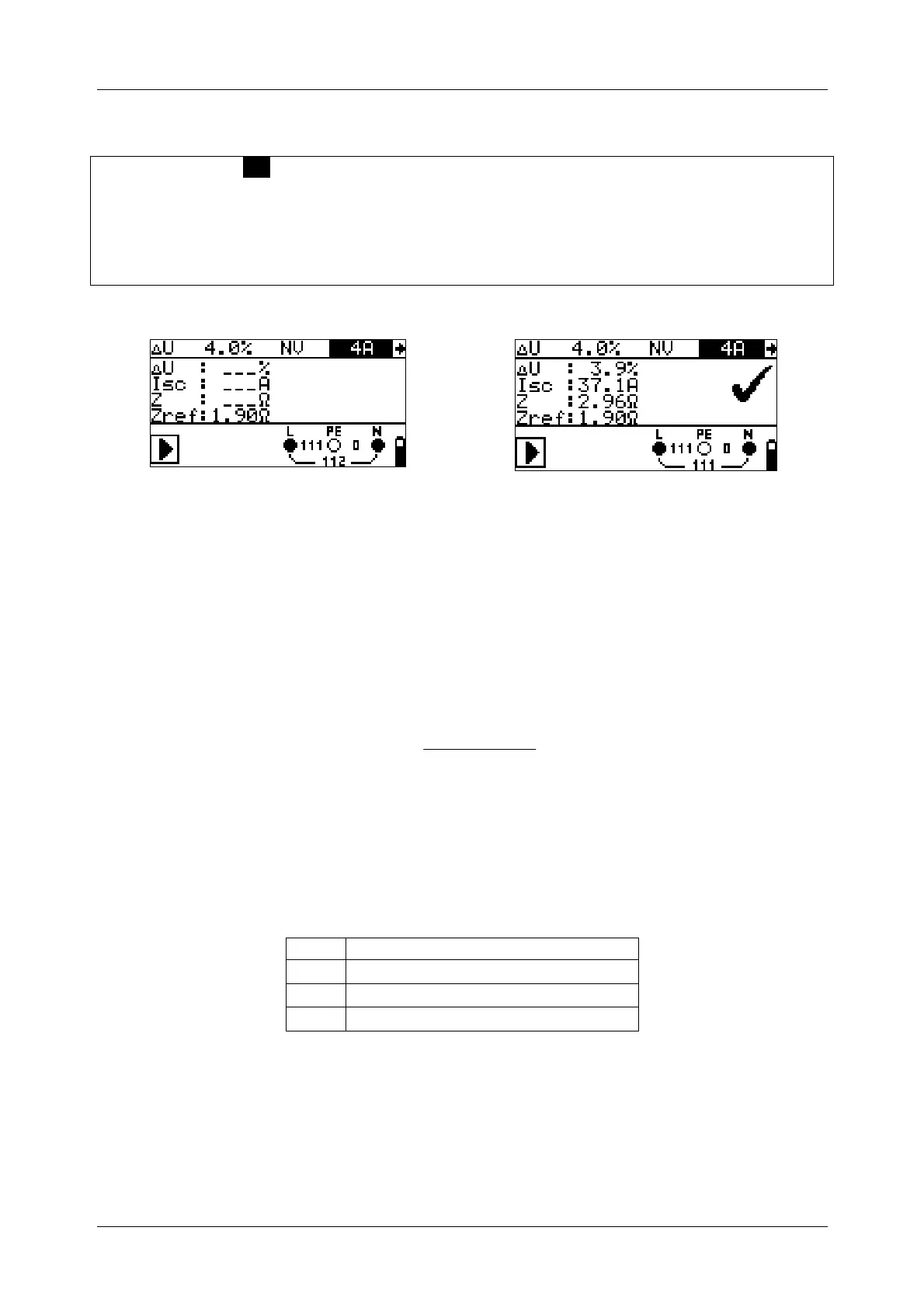
Step 1 - Zref Step 2 - Voltage drop
Figure 5.31: Examples of voltage drop measurement result
Displayed results:
ΔU ...........Voltage drop,
ISC............Prospective short-circuit current,
Z..............Line impedance at measured point,
Zref..........Reference impedance
Voltage drop is calculated as follows:
[]
100
)(
% ⋅
⋅−
=Δ
N
NREF
U
IZZ
U
where:
ΔU........ calculated voltage drop
Z………impedance at test point
Z
REF
…...impedance at reference point
I
N
………rated current of selected fuse
U
N
…….nominal voltage (see table below)
U
n
Input voltage range (L-N or L1-L2)
110 V
(93 V ≤ U
L-PE
< 134 V)
230 V
(185 V ≤ U
L-PE
≤ 266 V)
400 V
(321 V < U
L-N
≤ 485 V)
Note:
If the reference impedance is not set the value of Z
REF
is considered as 0.00 Ω.
The Z
REF
is cleared (set to 0.00 Ω) if pressing CAL key while instrument is not
connected to a voltage source.
I
SC
is calculated as described in chapter 5.6.1 Line impedance and prospective
short circuit current.