S
Sarah ColeAug 16, 2025
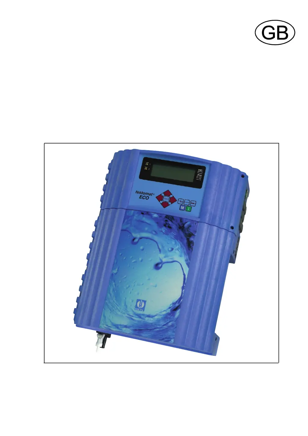
What to do if Testomat ECO Measuring Instruments shows low water pressure?
- FfitzgeraldnormaAug 16, 2025
If your Testomat Measuring Instruments indicates low water pressure, several factors could be the cause. First, check the water inlet if the LED "IN" is lit. Also, the inlet pressure may be too low due to an oxidised connector of the inlet valve. The overflow reagent might not be active, so try cleaning the filter strainer. If these steps don't resolve the issue, consider replacing the valve block, extracting the pressure regulator valve, or carrying out an adjustment.